71
10. MELite Operations
MELites, simplified M/Es, can be assigned to LINE1 or LINE2. First, attach an AUX bus to an MELite.
MELite mixed images can also be used as input sources on M/E1 and M/E2 (re-entry).
FLEXaKEY1-4 can be displayed on MELite mixed images. Therefore the switcher can provide up to 4
M/E with a key for each. (If the HVS-49IO expansion card is installed, MELite3 and 4 are added to the
switcher and a 6 M/Es equivalent system becomes available.)
See the table below for MELite configuration details.
(*1) If HVS-49IO options installed
MELite re-entries are available on M/E1 and M/E2, but not on MELite.
10-1. Setting up an MELite
1. Attach an AUX bus to an MELite
2. Use the SEL BUS button to assign the AUX bus (MELite assigned) to LINE 1 or LINE2.
The following example shows how to attach AUX5 to MELite1 and assign AUX5 to LINE2.
(1) Open the [SETUP > OUTPUT > MELite] menu. Turn F1 to select AUX05 for MELite1 ASSIGN.
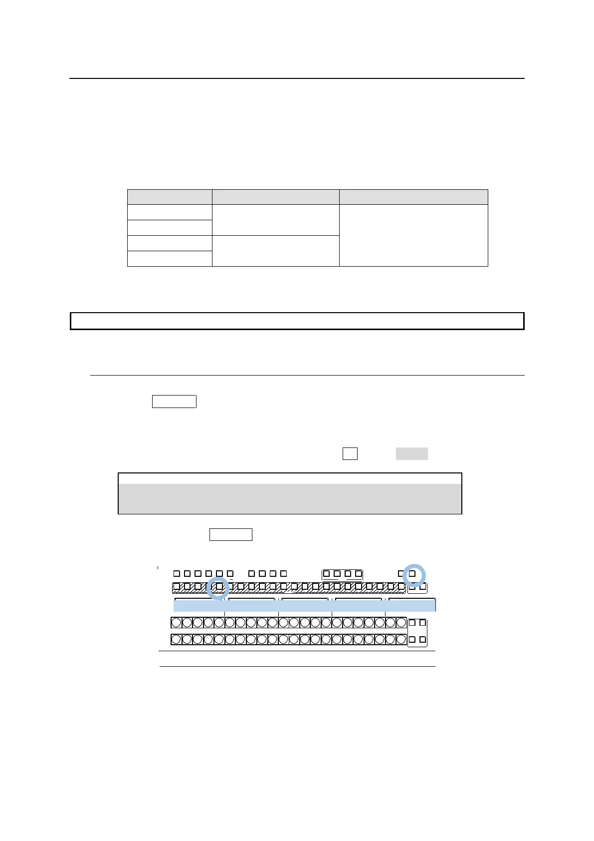
(2) Press and hold down SEL BUS in the LINE 2. Selectable names (M/E1, M/E2 and AUX1-12)
are displayed above the KEY/FLX row. Press the button above “AUX05 (MELite1).”
1 2 3 4 5 6 7 8 9 10 11 12 13 14 15 16 17 18 19 20 21 22
1 2
1 2
BUS FUNC
1 2 3 4 5 6 7 8 9 10 11 12 13 14 15 16 17 18 19 20 21 22 1 2
BUS FUNC
SEL BUSBUS DISP
MACRO
BUS RE C ATTACH DETACH
KEY/FLX
FLX 4FLX 3FLX2FLX11 2
UTILITY
KEY1 KEY2 KEY3 K EY4
MELite1 operation can now be performed in LINE 2.
MELite1 Mixed Images
MELite1 PGM and PVW images can be assigned to any outputs including Multiview images
except ME mixed outputs.
MELite 1 signal selection and transitions can be performed as the LINE 2 background bus.