179
25-2-5. Tally Output Settings (Tally Units)
Up to 5 tally units can be connected. This section explains how to set up TALLY1 (the tally unit
1) as an example.
Selecting Tally Color for an Output Bus
See Sec. 25-2-1 "Tally Color Settings." The Tally Color settings made in this menu are shared
with those for the GPI/TALLY OUT connectors and Tally Units.
Setting Pin Assignments for TALLY1
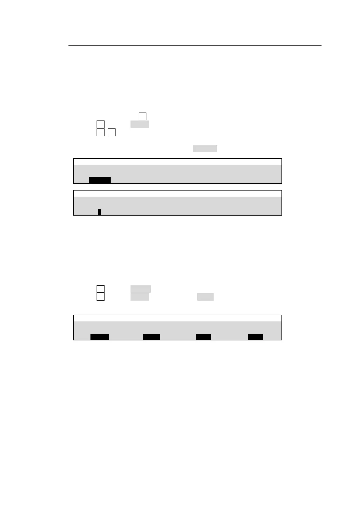
(1) Open the [SETUP > GPI TALLY > TALLY UNIT1] menu.
(2) Go to PAGE 2. Turn F1 to select the pin number.
(3) Turn F2 to select TALLY under TYPE.
(4) Turn F3, F4 to select a tally color and signal.
(5) Assign tallies to other pins in the same manner.
(6) Go back to PAGE 1. Set TALLY UNIT to ENABLE to enable TALLY UNIT1.
SETUP > GPI TALLY > TALLY UNIT1
SETUP > GPI TALLY > TALLY UNIT1
Setup other tally units. See the HVS-TALOC/TALR 20/32 operation manual for details on tally
connection and operation.
Connection Settings with Tally Units (RS-422 port setting)
Tally units are connected in series to the switcher via RS-422 port (Port 2 in this example). The
connection settings with Tally Units are set in the menu as shown below.
(1) Open the [SETUP > SYSTEM > RS-422] menu.
(2) Turn F1 to select PORT2.
(3) Turn F2 to select TALLY. Set the parity to EVEN. Set the baud rate to 38,400 bps.
(4) Reboot the HVS-490. (See Sec. 24-4. Reboot and Initialization.)