28
3-4. Interfaces
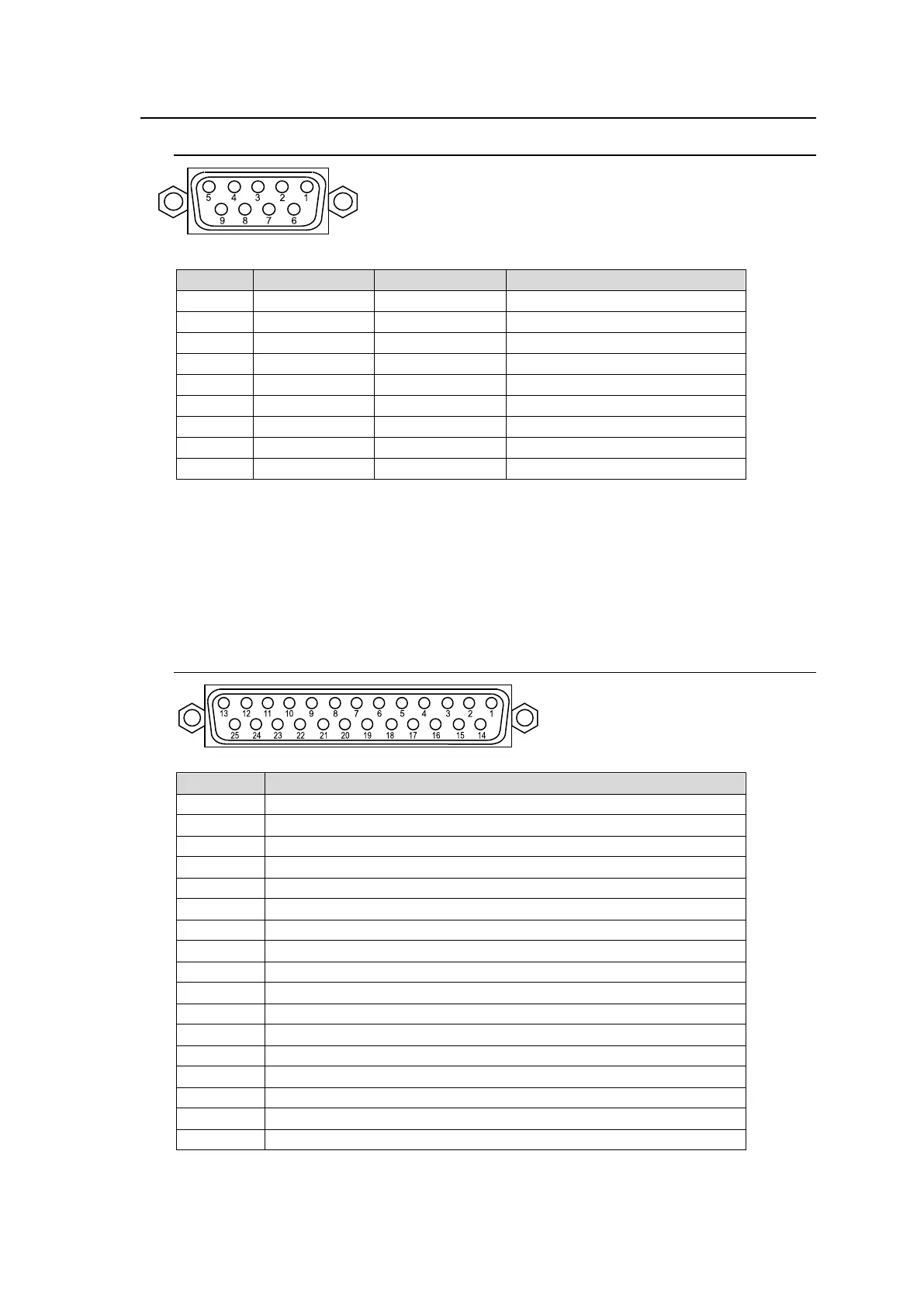
3-4-1. RS-422
Connector Pin Assignment Table
RS-422 ports are used for external device connections. See the associated chapters to
configure connections.
Router: See Sec. 25-3. “Router Control.”
Editor: See Sec. 25-6. “Editor Control”.
VTR: See Sec. 25-7. “VTR Control”.
VDCP: See Sec. 25-8. “VDCP Operation”.
3-4-2. GPI IN/ALARM
Connector Pin Assignment Table
M/E1 BKGD AUTO TRANS (default setting)
M/E1 KEY1 AUTO TRANS (default setting)
M/E1 KEY2 AUTO TRANS (default setting)
M/E1 KEY3 AUTO TRANS (default setting)
M/E1 KEY4 AUTO TRANS (default setting)
M/E2 BKGD AUTO TRANS (default setting)
M/E2 KEY1 AUTO TRANS (default setting)
M/E2 KEY2 AUTO TRANS (default setting)
M/E2 KEY3 AUTO TRANS (default setting)
M/E2 KEY4 AUTO TRANS (default setting)
FAN ALARM output (Common)
Not used (default setting)
POWER ALARM output (Common)
The pin functions are freely assignable. (See Sec. 25-1-1. “GPI IN.”)
* Maximum rating current for each pin is 0.5 A.
9-pin D-sub (female)
with inch screws
25-pin D-sub (female)
with inch screws