188
25-5. AUX Bus Control Box (HVS-AUX16A/16B /32A/64A)
HVS-AUX16A/16B/32A/64A units allow users to remotely change AUX output signals or recall
events of the switcher. A single AUX Box can manage all AUX outputs. Up to 16 (32 with SHIFT)
actions can be assigned to buttons on HVS-AUX16A/16B, 32 (64 with SHIFT) on HVS-AUX32A
and 64 on HVS-AUX64A. Up to 12 AUX units can be connected to the switcher.
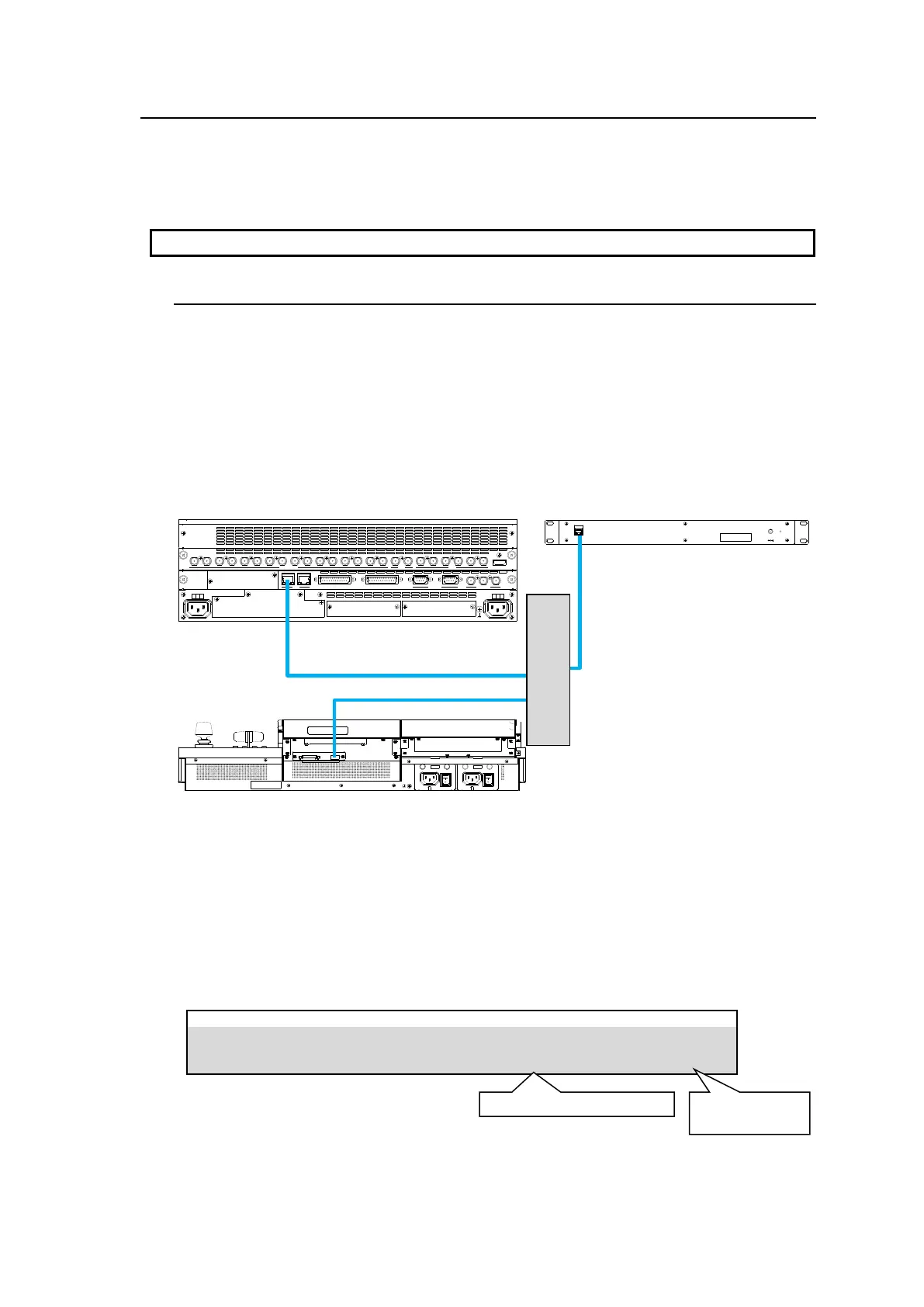
A LAN cable is required for the AUX box connection.
25-5-1. Connecting AUX Boxes
AUX boxes should be connected to the switcher using an Ethernet hub and LAN cables.
AUX ID Number
AUX ID numbers from 1 to 255 are used to uniquely identify an AUX box.
To connect to HVS-490 units, use ID1 to ID12. (Default setting: ID1)
The ID numbers should not be duplicated when connecting to a switcher.
In an AUX box, specify the IP address of the HVS (OU) port on the HVS-490 as a switcher IP
address. (Default: 192.168.0.10)
See the "HVS-AUX16A/16B/32A/64A Operation Manual" for more details.
Checking AUX Box Connection
The following example shows how to check the connection between AUX Box and the
switcher.
(1)Open [SETUP > AUX UNIT > UNIT1(UNIT2-12)] menu PAGE 1. (Select the Unit ID
assigned to the AUX unit. UNIT1 in this operation example)
(2) Once the connection is established, the product MAC address and the number of buttons
are displayed as shown below.
GPI I/O HVS LAN
POWER1
AC100-240V 50/60Hz IN
POWER
ON
OFF
POWER2
AC100-240V 50/60Hz IN
POWER
ON
OFF
SDI INPUT HDMI
65431 21615141312111098765431 2 21
M/E AUX
OPTION SLOT BOPTION SLOT A
AC100-240V 50/60Hz IN
2 1
AC100-240V 50/60Hz IN
REF IN REF OUT
GENLOCKGPI/TALLY OUTGPI IN/ALARMLAN
HVS(OU) EXT
1 2
RS-422