184
25-3-6. ROUTER LINK
The Router Link function allows you to switch a crosspoint on a router by pressing a switcher
bus button when inputting video from the router.
The following example will help to explain how to set up and use this function.
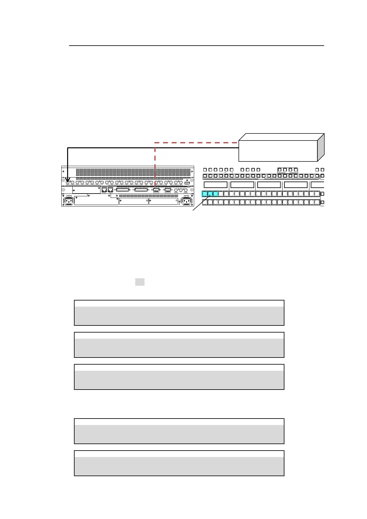
In the connection example below, the DST4 video is input to the switcher INPUT1. The system
will be set up so that if the switcher bus button 1, 2 or 3 is pressed, SRC7, SRC8 or SRC9
video is respectively sent to the switcher.
If Router Link is enabled, pressing a linked bus button sends a signal switch command to a
router and the switcher receives the specified video from a router even if a different video is
assigned to the associated destination channel on the router.
* Router Link function can be applied to each bus. If assignments are different for A, B,
PGM and PST buses, to use the ROUTER LINK function in another bus, a router
connection is required. (See Sec. 9-2-1. “M/E Bus Type.”)
Router Link Settings
(1) Open [SETUP > ROUTER > XPT LINK] menu PAGE 1.
Turn XPT LINK to ON. Set up RTR XPT (router crosspoint) and SRC (source) pairs as
shown below.
SETUP > ROUTER > XPT LINK
SETUP > ROUTER > XPT LINK
SETUP > ROUTER > XPT LINK
(2) Open the [PANEL > BUS ASSIGN > LEVEL1] menu. Assign crosspoints, RX001, RX002
and RX003, to bus buttons, 1, 2 and 3, as shown below.
PANEL > BUS ASSIGN > LEVEL1
PANEL > BUS ASSIGN > LEVEL1
OUT4 (DST4)
OUT5 (DST5)
OUT6 (DST6)
Router link buttons on the A bus
SDI INPUT HDMI
65431 21615141312111098765431 2 21
M/E AUX
OPTION SLOT BOPTION SLOT A
AC100-240V 50/60H z IN
2 1
AC100-240V 50/60H z IN
REF IN REF OUT
GENLOCKGPI/TALLY OUTGPI IN/ALARMLAN
HVS(OU) EXT
1 2
RS-422
1 2 3 4 5 6 7 8 9 10 11 12 13 14 15 16 17 18 19 20 21 22
1 2
1 2
BUS FUNC
1 2 3 4 5 6 7 8 9 10 11 12 13 14 15 16 17 18 19 20 21 22 1 2
BUS FUNC
SEL BUSBUS DISP
MACRO
BUS REC ATT ACH DET ACH
KEY /FLX
FLX4FL X3FLX2FL X11 2
UTILIT Y
KEY1 KE Y2 KE Y3 KEY4