182
25-3-4. Crosspoint Switches using Bus Buttons
To execute the following commands using Bus Buttons on LINE 2:
Connect Source channel 2 to Destination channel 1.
Connect Source channel 4 to Destination channel 2.
* Router Level setting in the menu is applied to bus button crosspoint switches.
First change LINE 2 to ROUTER mode, then switch crosspoints.
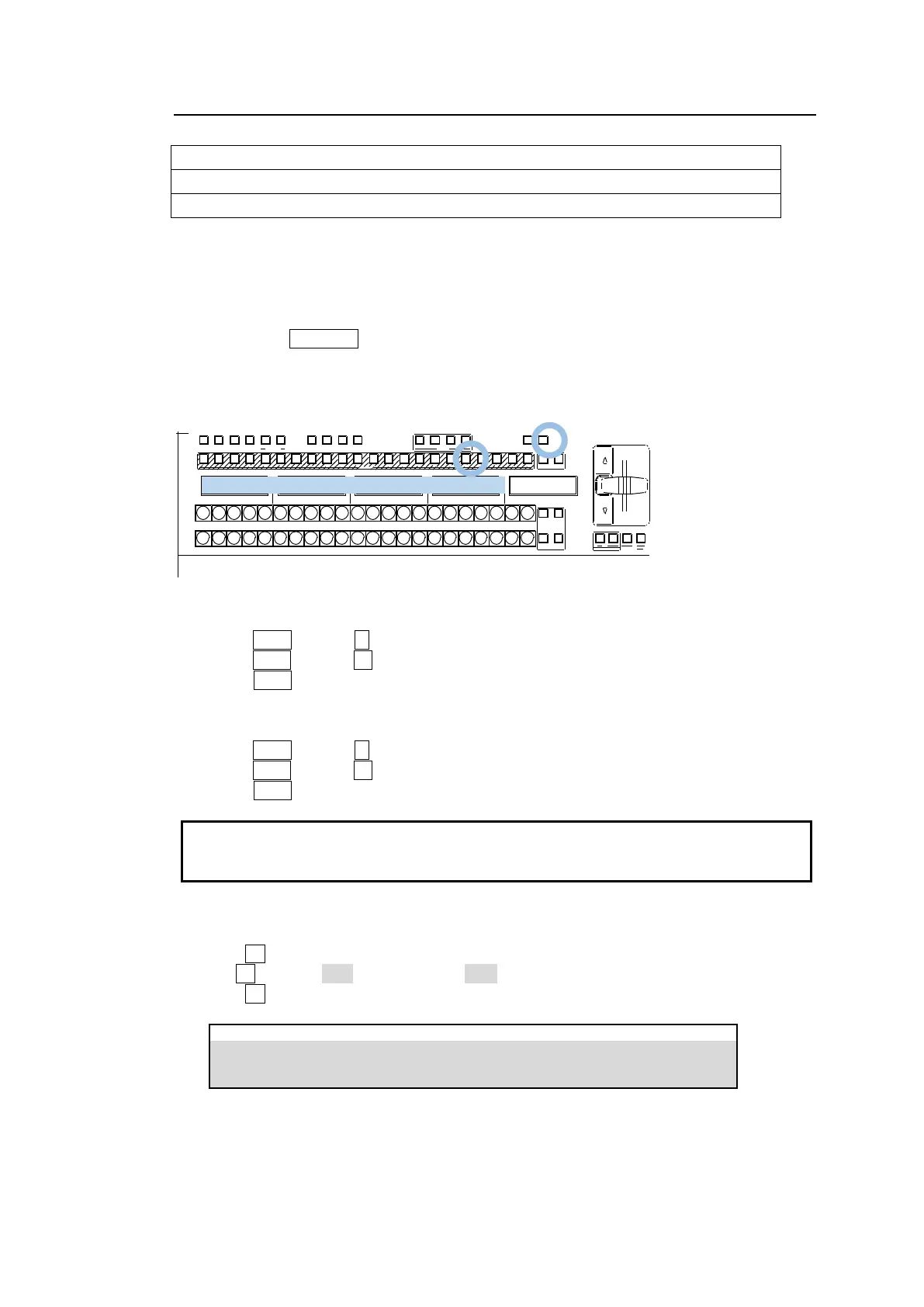
Changing LINE 2 to Router mode
(1) Hold down SEL BUS in the LINE2 section on the control panel. The "NONE", "M/E1",
"M/E2", "AUX1-12" and "ROUTER" indications are displayed beneath the KEY/FLX row.
(2) Press the button above the "ROUTER" indication on the KEY/FLX row.
DIRECTION
1 2 3 4 5 6 7 8 9 10 11 12 13 14 15 16 17 18 19 20 21 22
1 2
1 2
BUS FUNC
1 2 3 4 5 6 7 8 9 10 11 12 13 14 15 16 17 18 19 20 21 22 1 2
BUS FUNC
SE L BUSBUS DISP
MACRO
BUS RE C ATTACH DE TACH
KE Y/FLX
FLX 4FLX3FLX2FLX11 2
UTILITY
KEY1 KEY2 KEY3 KEY4
To connect Source channel 2 to Destination channel 1
(1) Press D001 (Default 1 ) on the PGM bus. The button light will turn on.
(2) Press S002 (Default 12) on the PGM bus.
(3) When S002 turn on, Source 2 is connected to Destination 1 on the router.
To connect Source channel 4 to Destination channel 2
(1) Press D002 (Default 2 ) on the PGM bus. The button light will turn on.
(2) Press S004 (Default 14) on the PGM bus.
(3) When S004 turns on, Source 4 is connected to Destination 2 on the router.
Destination (DXXX), Source (SXXX) or other router function names are shown on the
displays above bus buttons. Functions in the top row are assigned to the PGM bus buttons,
and functions in the bottom row to the PST bus buttons.
<Changing Router Function Assignments>
(1) Open the [PANEL > ROUTER BUS ASSIGN > ABUS(BBUS)] menu.
(2) Turn F1 to select a button.
(3) Turn F2 to select DST (destination) or SRC (source).
(4) Turn F3 to select a channel number.
PANEL > ROUTER BUS ASSIGN > ABUS