16
2. Connection and Basic Operation
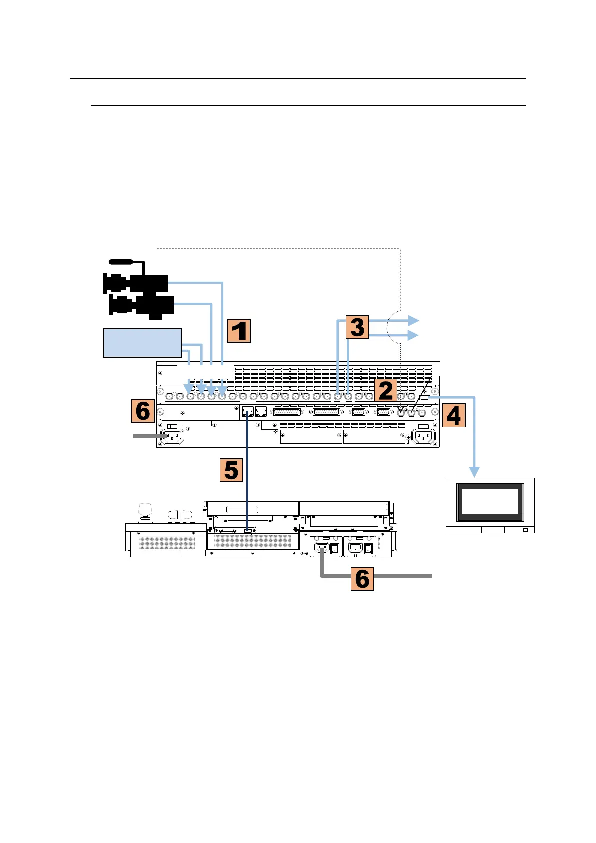
2-1. Basic Connection Example
(1) Connect video sources (SDI signals) from cameras or other video devices to the Main Unit.
(2) Input a reference signal. Terminate the other connector with a 75-ohm terminator if it is not
looped-through.
(3) Connect downstream devices to provide combined output video (PGM images in SDI format).
(4) Connect a monitor with the HDMI connector (for monitoring preview or multiview images).
(5) Connect the Main Unit (MU) and Control Panel (OU) using the supplied control cable.
(6) Supply AC power to the Main Unit and Control Panel using the provided power cords.
GPI I/O HVS LAN
POWER1
AC100-240V 50/60Hz IN
POWER
ON
OFF
POWER2
AC100-240V 50/60Hz IN
POWER
ON
OFF
SDI INPUT HDMI
65431 21615141312111098765431 2 21
M/E AUX
OPTION SLOT BOPTION SLOT A
AC100-240V 50/60Hz IN
2 1
AC100-240V 50/60Hz IN
REF IN REF OUT
GENLOCKGPI/TALLY OUTGPI IN/ALARMLAN
HVS(OU) EXT
1 2
RS-422