39
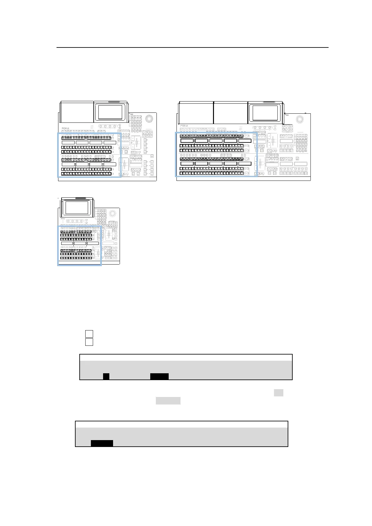
6-2. Mapping Video Sources to Bus Buttons
Bus button rows, comprising 18 buttons for each row on HVS-492OU units, 22 buttons on
HVS-492WOU and 12 buttons on HVS-492ROU, are used to select video sources. Primary and
optional video inputs, internally generated signals (black, mattes, etc.) can be freely assigned to
any buttons in the M/E1, M/E2 and AUX1-12 bus rows.
HVS-492OU HVS-492WOU
HVS-492ROU
ALARM
POWER1
POWER2
F1 F2 F3 F4
PAGE
1 2 3 4 5 6 7 8 9 10 11 12
KEY1 KEY2 KEY3 KEY4
AUX
UTILITY
1 2
PGM OUT1 OUT2 OUT3 PGM OUT1
M/E1 M/E2
OUT2 OUT3 MV1 MV2 MV3
AUX TRANSITION
CUT MIX WIPE
USER BUTTON
KEY1 KEY2 KEY3 KEY4 1 2 FLX1 FLX 2 FLX3 FLX 4
USER BUTTON
4 5 6
TRANSITION TYPE
AUTO C UT
KEY4
FLX4
KEY3 FLX3
KEY2 FLX2
KEY1 FLX1
BLACK
TRANS
KEY4
KEY3
KEY2
KEY1
TRANSITION TYPE
AUTO C UT
1 2 3
JOYSTICK
M/E2
ENTERCLEAR
0
+ / -
1 2 3
4 5 6
DEC
SD CARD
CONTROL
MEMORY
M/E1
INC
7 8 9
UTILITY
KEY/FLX
1 2 3 4 5 6 7 8 9 10 11 12
1 2 3 4 5 6 7 8 9 10 11 12
1 2 3 4 5 6 7 8 9 10 11 12
1 2 3 4 5 6 7 8 9 10 11 12
KEY AUX
Note that MELite1-2 must be assigned to LINE1 and LINE2 before use. See Sec. 9-1-1.
“Assigning an M/E to a LINE” for more details.
(1) Tap the PANEL tab, then BUS ASSIGN and LEVEL1 buttons to display the [PANEL > BUS
ASSIGN > LEVEL1] menu page.
(2) Tap a button in the right side of the menu screen to select a bus row.
(3) Turn F1 to select a bus button.
(4) Turn F2 to select a video source.
PANEL > BUS ASSIGN > LEVEL1
(5) Users can inhibit operation of specific bus buttons. First, turn INHIBIT to ON for each button
Then, set BUTTON INHIBIT to ENABLE in the [PANEL > BUS ASSIGN > ALL LEVEL] menu to
inhibit bus buttons. The INHIBIT setting has no effect on the KEY/AUX and KEY/FLX rows.
PANEL> BUS ASSIGN > ALL LEVEL