180
25-3. Router Control
The switcher can connect and control a router. Router crosspoint switches can be performed on the
switcher's control panel. The router control is based on the HARRIS Pass-Through protocol.
In addition to router control, video titles on the router can be handed to the switcher if a FOR-A MFR
series router is connected. (*1)
Manageable number of sources, destinations and levels are:
Connect a router to an RS-422 port on the switcher using an RS-422 straight-through cable. Then
configure the RS-422 port for router control. Refer to the MFR Series Operation Manual for details
on MFR router settings.
*1 Although MFR routers will be fully supported in the future, limited control over MFR routers is
possible at present by selecting HVS-2000 under Switcher in the [Tally System Settings >
Device Select] in the MFR Web-based Control menu.
Bus control limitations
CK1-4, SUB_EFF1-4, AUX13-20
Unselectable bus
(HVS-490 unsupported bus)
IN41-48, ME3, MV4, MELITE5-6, AUX1-12 (SOURCE)
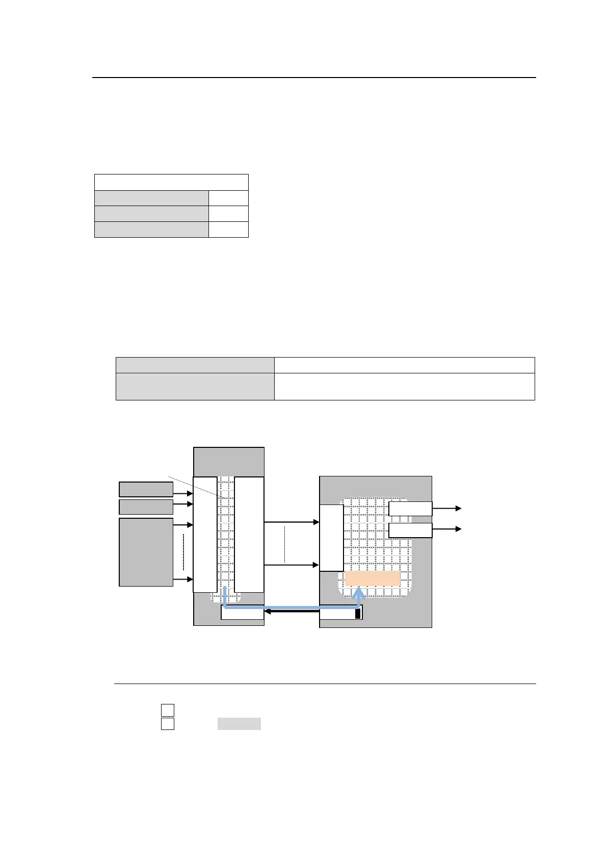
<Connection example: Connecting MFR Main unit to HVS-490>
25-3-1. Assigning a Router Channel to an RS-422 port
(1) Display the [SETUP > SYSTEM > RS-422] menu
(2) Turn F1 to select a port for connecting a router.
(3) Turn F2 to select ROUTER.
(4) Set BAUDRATE and PARITY according to the router.
IN
01
02
|
|
|
|
|
|
|
16
OUT
01
02
|
|
|
|
|
|
|
16