21
3. Panel Descriptions
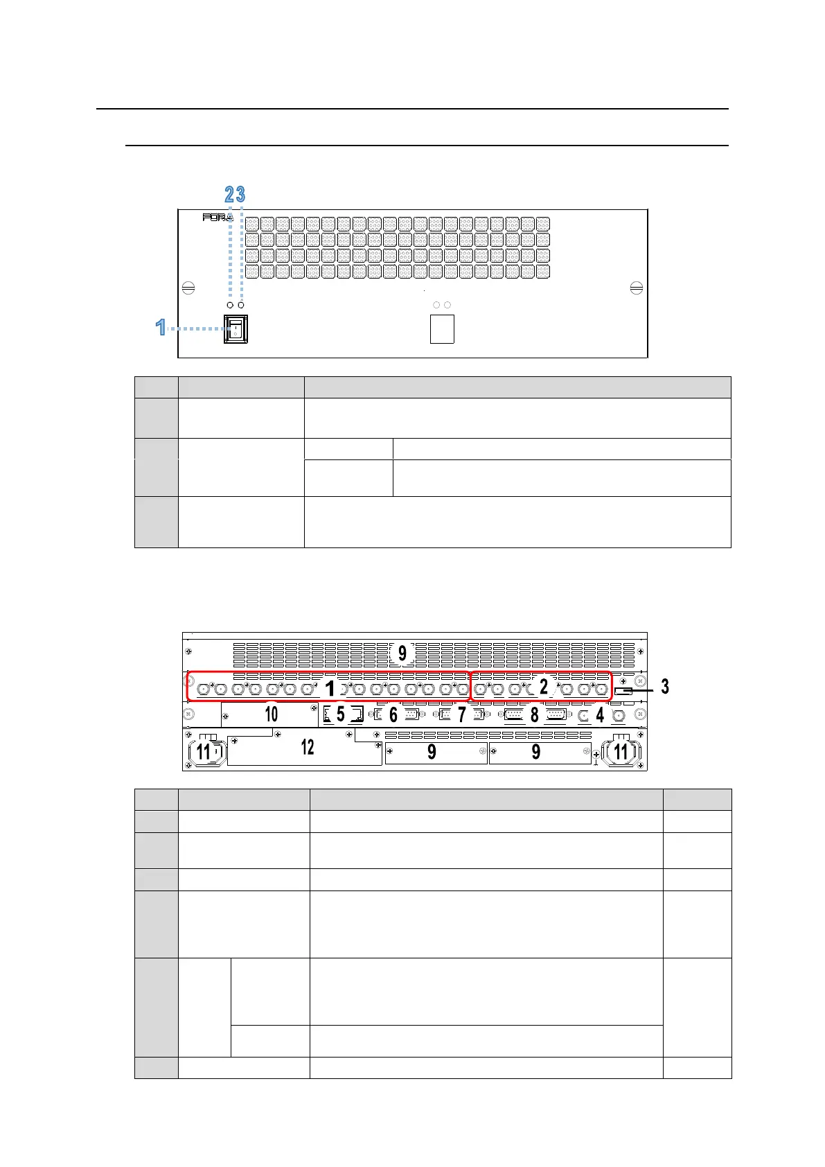
3-1. HVS-490
Front Panel
POWER 1 POWER 2
ALARMPOWER 2ALARMPOWER 1
HVS-490
DIGITAL VIDEO SWITCHER
Used to turn each power unit On/Off.
Turns on all active power units.
Power is supplied to the unit.
Power is not supplied to the unit. Or power unit is not
installed.
Power and fan alarm. Lit red when an error occurs. In such cases,
power off the unit and consult your FOR-A supplier. The indicator is
normally unlit.
* Power Supply Unit 1 is standard and Unit 2 is optional.
Rear Panel
SDI INPUT HDMI
65431 21615141312111098765431 2 21
M/E AUX
OPTION SLOT BOPTION SLOT A
AC100-240V 50/60Hz IN
2 1
AC100-240V 50/60Hz IN
REF IN REF OUT
GENLOCKGPI/TALLY OUTGPI IN/ALARMLAN
HVS(OU) EXT
1 2
RS-422
Used to input video signals: HD-SDI x 16 (BNC)
Used to output video signals: HD-SDI x 8
(M/E1-2 and AUX1-6) (BNC)
Used to output video in HDMI format: HDMI x 1
Used to input and output a genlock signal; tri-level sync
or black burst. The other REF IN connector is used as a
loop-through output connector. It must be 75-ohm
terminated if not looped-through. (BNC)
Used for control panel (HVS-492OU/ 492WOU/
492ROU) connection. (RJ-45) Use the control cable
supplied with the OU to connect to the HVS LAN port on
the OU.
Uses for additional LAN connection (RJ-45)
Used for GPI input. (25-pin D-sub, female)