HVS490_OU-SETUPGUIDE-E-4.DOCX
HVS-490
HVS-491OU/492OU/492WOU/492ROU
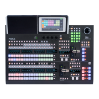
1. Connection
(1) Connect SDI video signal inputs.
(2) Input a reference signal. Terminate the
other connector with 75-ohm,
if it is not looped-through.
If no reference signal is input, refer to
Sec. 2 “Setup” to turn on frame synchronizers.
(3) Connect combined SDI video signal outputs.
(4) Use the supplied LAN cable to connect
HVS-490 LAN HVS (OU) to HVS LAN on the control panel.
(5) Supply power to HVS-490 and the control panel
respectively using the supplied AC cables.
(6) Turn on power switch(es) on the rear control panel.
(7) Turn on power switch(es) on the
HVS-490 front panel.
* HDMI outputs can display input sources,
as well as combined images such as
preview, program or multiview.
* An Ethernet hub can be used for LAN connections.
2. Setup
Select the HVS-490 for MU
(1) A menu is displayed on the control panel at power ON.
(2) Tap the PANEL tab on the touch panel menu screen.
(3) Tap NETWORK to display the [PANEL > NETWORK > NETWORK] menu.
(4) Press the down arrow (▼) button to go to PAGE 2. Turn F1 to select HVS-490 and press F1. Tap YES on the confirmation
dialog box to restart the control panel. After restart, control panel buttons will light up when the control panel is connected to HVS-
490. If the buttons stay unlit, set the MU (HVS-490) IP address (LAN HVS(OU) port). Press F2 on the [PANEL > NETWORK >
NETWORK] menu PAGE 2. Enter the address using the keypad and press Enter.
Select the System Signal Format
(1) Open the [SETUP > SYSTEM > FORMAT] menu.
(2) Turn F1 to select the signal format, then press F1. Tapping YES restarts the switcher. After a restart, the new format is applied.
(3) Open the [SETUP > SYSTEM > FORMAT] menu and turn F2 .to select an aspect ratio.
Set Date and Time
Open the [SETUP > SYSTEM > TIME] menu to set the date.
Go to PAGE 2 to set the time. Go to PAGE 3 to set the time zone and summertime on/off.
Turn Frame Synchronizer to ON
Turn on the frame synchronizer, if necessary.
(1) Open the [SETUP > INPUT > SIGNAL] menu.
(2) Turn F1 to select IN01. Turn F4 to set FS to ON.
(3) Turn F1 to select IN02. Turn F4 to set FS to ON. Set FS to ON for other inputs in the same manner.
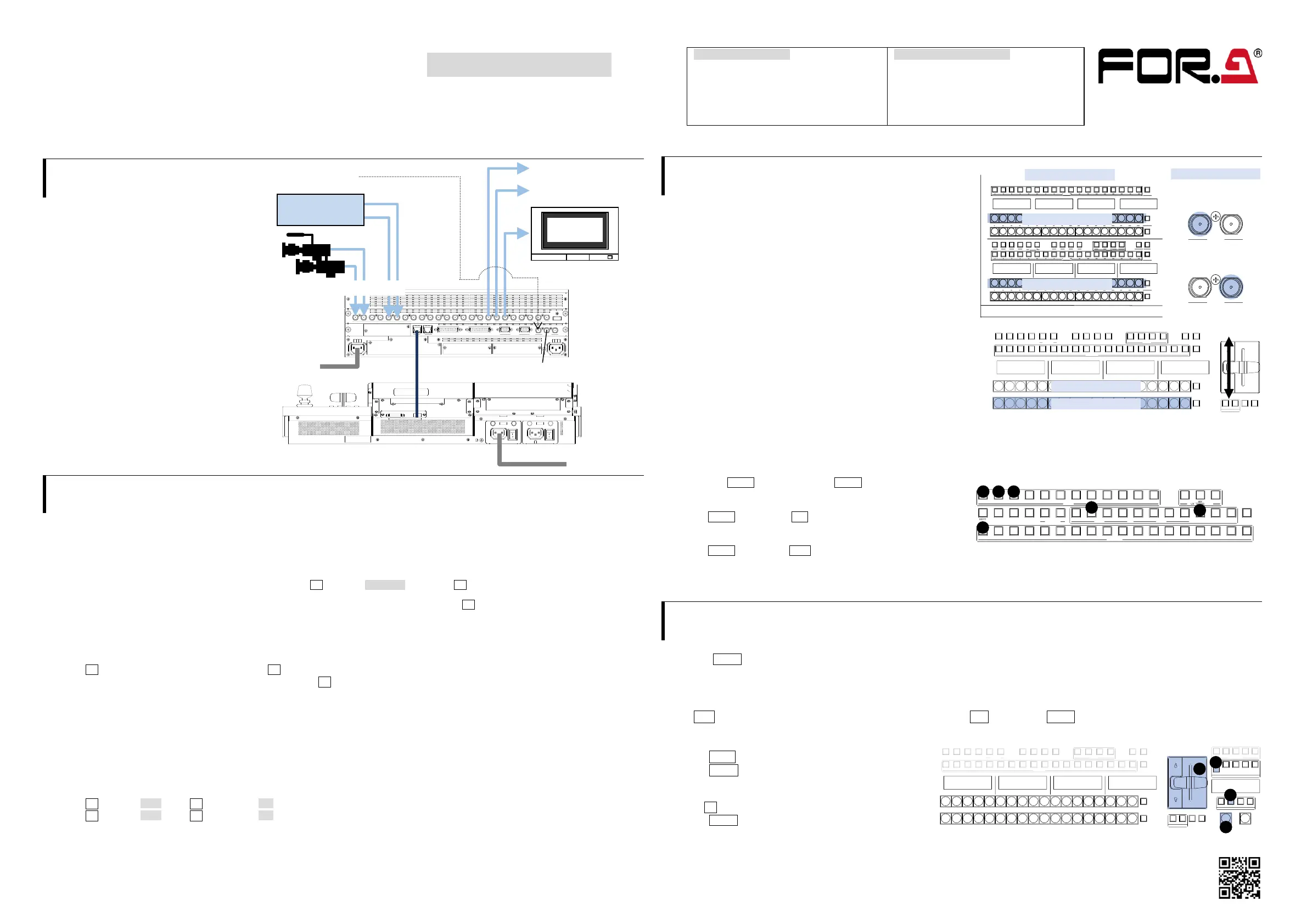
3. Select Output Video
Select an M/E1PGM Video
Press a bus button on the M/E1PGM row.
The corresponding video will appear on M/E1 output.
Select an M/E2PGM Video
Press a bus button on the M/E2PGM row.
The corresponding video will appear on M/E2 output.
Change the M/E2PGM Video
(1) Press a button on the M/E2 PST row to select a next video.
(2) Move the fader from end to end.
The M/E2 output screen will change to the next video.
This is called a "background transition."
(3) Move the fader from end to end again. The M/E2 output
screen changes to the previous video.
* The PGM and PST signal selections switch as soon as the
PGM video changes, and the next video can always be selected
on the bottom (PST) row. The M/E1 bus operates in the same manner as the M/E2 bus.
Select AUX Output Video
(a) To display the M/E1 Preview video on the AUX1 screen, locate
the bus selection buttons and KEY/AUX bus* on the M/E1 bus
and press AUX1, then press M/E1 OUT1.
(b) To display the Input 1 video on the AUX2 screen,
press AUX2, then press 1 on the KEY/AUX bus*.
(c) To display a multiviewer video on the AUX3 screen,
press AUX3, then press MV1.
* KEY/FLX/AUX bus (HVS-491OU)
4. Perform Background Transitions
Select a next video on the PST bus.
Verify that BKGD is turned on. If not, press the button to turn on the button light.
Transitions
- CUT - MIX
Press CUT. The background image changes instantly. Press MIX. Then press AUTO. (Or move the fader from end to end.)
- Pattern
(1) Press WIPE.
(2) Press BKGD twice quickly to display the
[M/E FLEXaKEY > M/E2 > BKGD PGM > TRANS >
TRANS] menu.
(3) Turn F4 to select a pattern.
(4) Press AUTO. (Or move the fader from end to end.)
 Loading...


