25
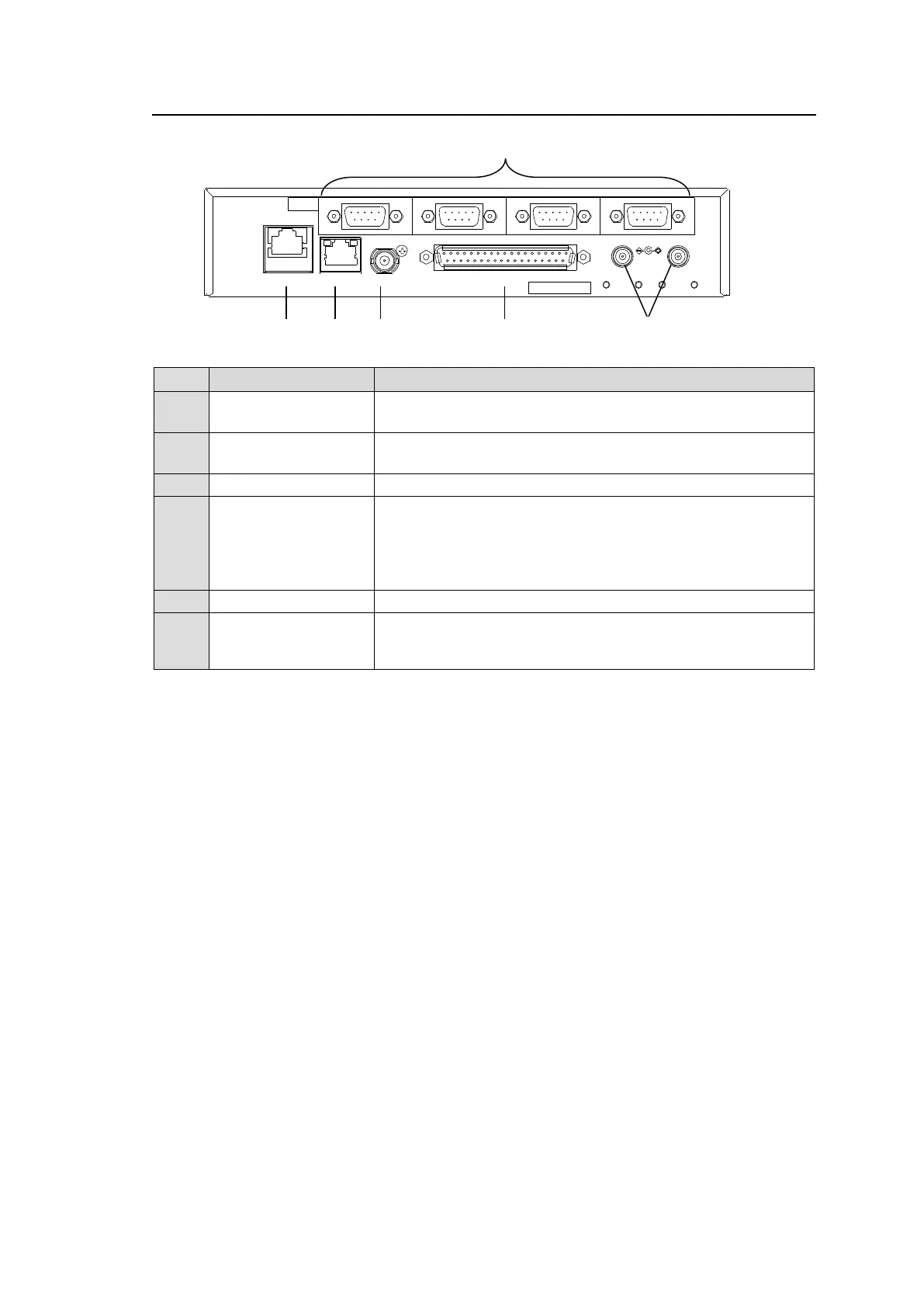
2-3-2. Rear Panel
Used to connect to a PC or other external unit.
An Ethernet port (10/100BASE-TX RJ-45)
Used to connect to an MFR main unit.
An Ethernet port (10/100/1000BASE-T RJ-45)
Used to input a reference signal (BB or Tri-level sync signal)
Used to input/output GPI signals for external control.
(32 total assignable inputs and outputs)
Pin assignments are the same as those of the MFR-GPI
connectors.
See section 2-2-3 "Interfaces (MFR-GPI)."
Used to supply 12 V DC power.
Used for control via an RS-422 interface.
Pin assignments are the same as those of the MFR main unit.
See section 2-1-3. “Interfaces."
SER. NO.
2
4
3
21
GPIREF INMFR-LANPC-LAN
1
DC12V IN
RS-422

 Loading...


