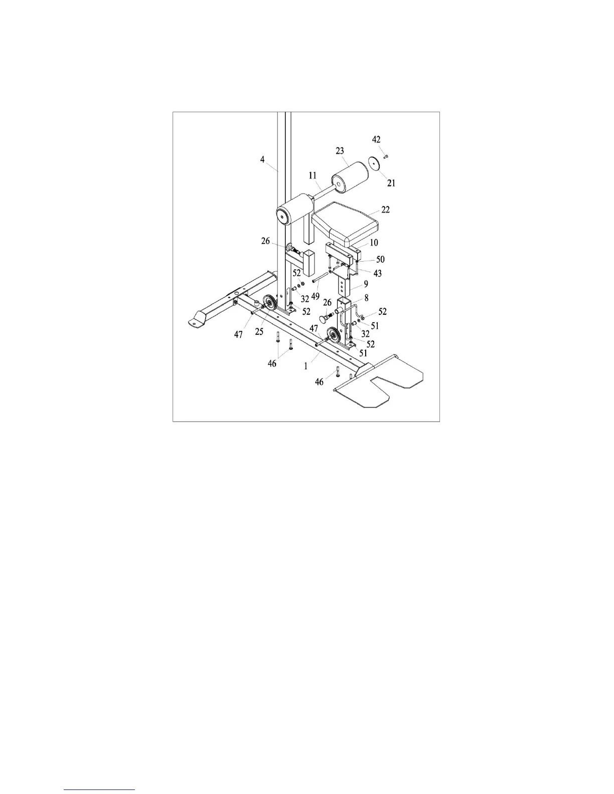
STEP 02
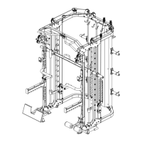
1. Attach upright-unit (4) and front support (8) to lower boom-unit (1) with square neck screws
M10*60 (46), washers 10 (51) and lock nuts M10 (52).
2. Attach a pulley (25) and two bushings (32) to upright-unit (4) with screw M10*70 (47), washers
10 (51) and lock nut M10 (52). The front support (8) is the same step.
3. Insert adjustable support (9) and footrest-unit (11) into port of upright-unit (4) and front support
(8), secure with fast pin (26).
4. Attach cushion support (10) to adjustable support (9) with screw M10*115 (49), washers 10 (51)
and lock nut M10 (52).
5. Attach cushion (22) to cushion support (10) with screws M8*80 (43) and washers 8 (50).
6. Push foam roller (23) onto each side of footrest-unit (11).
7. Attach sheathing (21) to footrest-unit (11) with screws M8*25 (42).