Next Generation Firewall Hardware Guide | Models N120W, N120WL,and N120L
Steps
1) Drill two holes 120mm (4.7 inches) apart in the wall in a horizontal orientation.
Make sure that you leave enough clearance around the appliance.
2) If required, insert nylon plugs into the holes.
3) Insert the two screws into the holes and tighten the screws.
Make sure that the screws are protruding from the wall to provide a firm mounting point for the appliance.
4) Align the mounting holes on the appliance with the screws, then place the appliance on the screws so that
the cables are below the appliance.
After the appliance is mounted on the wall and you have connected the cables, do not pull on the cables.
CAUTION
If you need to disconnect any cables after the appliance is mounted on the wall, hold the
appliance in place while you disconnect the cables.
Connect the cables
Connect the network and power cables.
Use at least CAT5e-rated cables for gigabit networks.
Network interfaces at both ends of each cable must have identical speed and duplex settings. These settings
include the automatic negotiation setting. If one end of the cable uses autonegotiation, the other end must also
use autonegotiation. Gigabit standards require interfaces to use autonegotiation. Fixed settings are not allowed at
gigabit speeds.
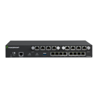
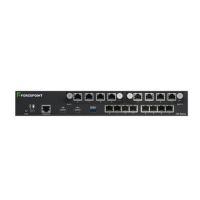
Connect network cables
Ethernet ports are mapped to interface IDs during the initial configuration. Determine which Ethernet ports to use
for connecting to your networks.
Steps
1) Connect network cables to the Ethernet ports.
If you use the plug-and-play configuration method for a single NGFW appliance, the appliance uses Ethernet
port 0 to contact the Installation Server.
If the appliance is a node in an NGFW Engine cluster, connect the cable for the heartbeat connection
between the nodes to Ethernet port 2.
2) Connect the cables to the ports that are used for the integrated switch.
Related concepts
How the integrated switch works on page 21
19