SHOP MANUAL Paragraph 12 (Cont.)
SO
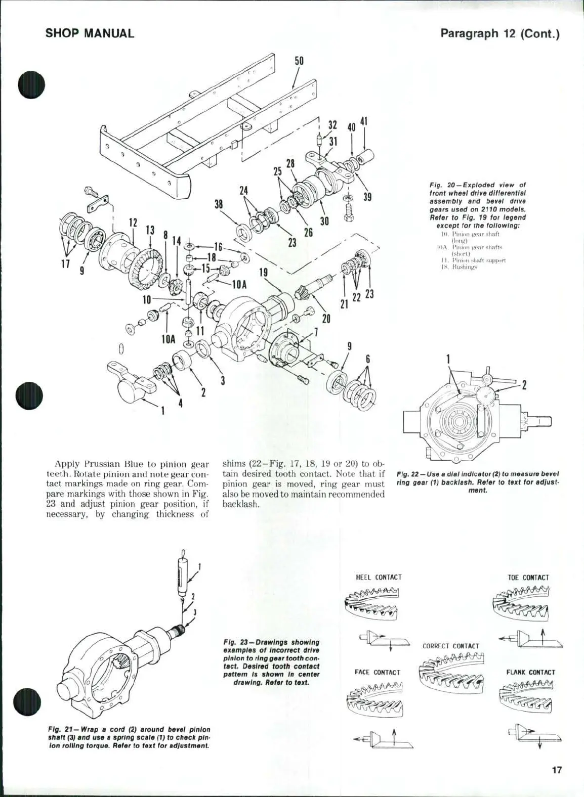
Fig. 20—Exploded view of
front wheel drive differentiai
assembiy and bevei drive
gears used on 2110 models.
Refer to Fig. 19 for iegend
except for the foiiowingi
!<i.
Pinion ^ear shaft
(long)
lOA. Pinion jrear shafts
(short)
U . Pinlim shaft support
IK. Bushings
Apply Prussian Blue to pinion gear
teeth. Rotate pinion and note gear con-
tact markings made on ring gear. Com-
pare markings with those shown in Fig.
23 and adjust pinion gear position, if
necessary, by changing thickness of
shims (22-Fig. 17, 18, 19 or 20) to ob-
tain desired tooth contact. Note that if
pinion gear is moved, ring gear must
also be moved to maintain recommended
backlash.
Fig.
22—Use a dial indicator
(2)
to measure bevel
ring gear (1) backlash. Refer to text for adiusP
ment.
HEEL COKTACT
TOE
CONTACT
Fig. 23—Drawings showing
examples of Incorrect drive
pinion to
ring
gear tooth
con-
tact. Desired tooth contact
pattern Is shown In center
drawing. Refer to text
Fig.
21 —Wrap
a cord (2) around bevel pinion
shaft (3) and use a spring scale
(1)
to check pin-
ion roiling torque. Refer to text for adiustment.