Paragraph
12
FORD
This will provide recommended bearing
preload adjustment.
On 1310, 1510, 1710, 1910
and
2110
models, attach left axle housing
to dif-
ferential center housing. Note that axle
shaft
(5
-
Fig, 18), bearing
(7)
and spacer
(8) must first be installed in axle housing
on 1710
and
1910 models. Position axle
housing vertically with differential hous-
ing up, making sure that the assembly
is
supported
by the
axle housing
and not
the axle shaft. Install differential
assembly into differential housing.
Be
sure that carrier bearing
is
correctly
located
in
axle housing and that there
is
clearance between ring gear and pinion.
Add shims (6-Fig.
18,
19
or
20)
if
nec-
essary. Position right axle housing (with
axle shaft, inner bearing and spacer
on
1710 and 1910 models) over differential
assembly using more shims
(17)
than will
be required
to
insure that there
is
clearance between axle housing and
dif-
ferential housing.
Use a
feeler gage
to
measure the gap between the two hous-
ings,
then remove right axle housing and
subtract shims from shim pack
(17)
equal to the measured gap. This will pro-
vide recommended bearing preload
ad-
justment. Adjust ring gear
to
pinion
backlash
as
outlined
in
paragraph
12,
12.
RING GEAR
TO
PINION
BACKLASH. Carrier bearing preload
should
be
correctly adjusted
as
outlined
in paragraph 11 before proceeding with
backlash adjustment.
To
check
and ad-
just backlash, proceed
as
follows:
On 1110 and 1210 models, backlash
is
checked with left axle housing removed
and right axle housing
and
differential
completely assembled.
On 1310, 1510,
1710,1910 and 2110 models, backlash
is
checked with right axle housing
re-
moved and left axle housing attached
t
differential housing. Axle shaft
(5
-
Fig!
18),
shims (16), inner bearing
(7) and
spacer
(8)
must
be
assembled
in
axle
housing on 1710 and 1910 models.
On all models, support axle housing in
a vertical position with differential
up.
Use
a
dial indicator to measure backlash
as shown
in Fig, 22.
Recommended
backlash
is
0,10-0.15
mm
(0.004-0.006
inch).
To
adjust backlash, move shims
between
the
axle housings until correct
backlash
is
obtained.
NOTE:
Do not Increase or decrease
overall thickness of shim pack as carrier
bearing preioad adjustment would be af-
fected.
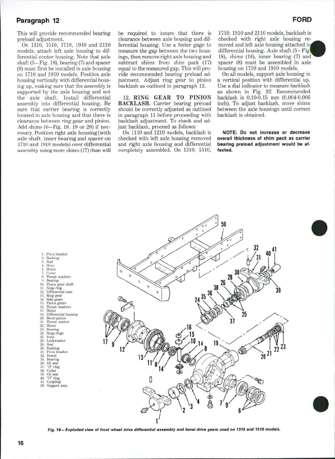
1.
F^ivot bracket
2.
Bushing
:i.
Seal
4.
Shim
H. Shims
7.
Cover
H, Thrust washers
i*. Bearing
10.
Pinion gear shaft
11.
Snap ring
12.
Differential case
13.
Ring gear
14.
Side gears
15.
Pinion gears
IH.
Thrust washers
17.
Shims
11).
Differential housing
20.
Bevel pinion
21.
Thrust washer
22.
Shims
23.
Bearing
24.
Snap rings
25.
Nuts
26.
Lockwasher
28.
Seal
30.
Bushing
31.
Pivot bracket
32.
Dowel
35.
Bearing
36.
Oil seal
37.
"0"
ring
38.
Collar
39.
Oil seal
40.
"0"
ring
41.
Coupling
50.
Support assy.
Fig. 19-Exploded view
of
front wheel drive differential assembly and bevel drive gears used on 1310 and 1510 models.
16