SHOP MANUAL
Paragraphs 34-37
injection pump mounting cap screws, set
pump control lever in middle of travel
and remove injection pump. Be sure to
retain any shims used between injection
pump and timing gear case for use in in-
stallation. Remove hydraulic pump as-
sembly. Remove crankshaft pulley.
Remove camshaft gear cover (46-Fig.
64),
nut (45) and governor weight
assembly (43). Remove injection pump
camshaft bearing cover (51). It may be
necessary to bump injection pump cam-
shaft (49) back as gear case is pulled for-
ward. Unbolt and remove timing gear
case (7) from front of engine.
To install gear case, reverse the
removal procedure. Note that crank-
shaft pulley is splined to crankshaft and
timing marks on pulley and end of
crankshaft must be aligned. Tighten
pulley retaining cap screw to 48-58
N * m
(36-43 ft.-lbs.) torque.
Models 1210-1310
34.
To remove timing gear case, first
drain cooling system and engine oil.
Remove the radiator and cooling fan.
Remove the exhaust muffler and alter-
nator. Remove the hydraulic pump.
Remove injection pump high pressure
fuel lines. Disconnect throttle control
rod from governor lever. Remove injec-
tion pump mounting bolts, then raise in-
jection pump and disconnect governor
link from pump control rack. It is not
necessary to remove injection pump.
Remove the crankshaft pulley. Unbolt
and remove timing gear case from front
of engine.
To reinstall gear case, reverse the
removal procedure. Be sure that dowel
pin (2-Fig. 67) in gear case engages
hole in the oil pump front cover. Make
certain that timing marks on crankshaft
pulley and end of crankshaft are aligned.
Models 1500-1510-1700-1710-
1900-1910-2110
35.
To remove timing gear case
(7-Fig. 65), first drain cooling system
and engine oil. Remove the radiator and
cooling fan. Remove the alternator
assembly. On 1510 and 1710 models,
remove the water pump. On 2110
models, remove the power steering
pump (if equipped). On all models,
remove the hydraulic pump and filter
assembly. Remove the crankshaft pul-
ley. Unbolt and remove timing gear case
from front of engine.
To reinstall, reverse the removal pro-
cedure. Be sure that timing marks on
crankshaft pulley and end of crankshaft
are aligned. Tighten pulley retaining cap
screw to 49-59 N-m (36-43 ft.-lbs.)
torque.
CAMSHAFT AND
CAM FOLLOWERS
Models 1100-1110-1200-1300
37.
To remove the camshaft, it is
necessary to raise the mushroom type
cam followers away from cam lobes so
that camshaft can be withdrawn to the
front. If proper tools are available to
raise and hold the cam followers up, en-
gine can remain attached to the clutch
housing.
Drain engine coolant and oil. Refer to
paragraph 26 and remove the engine.
25
46
:.^^
54
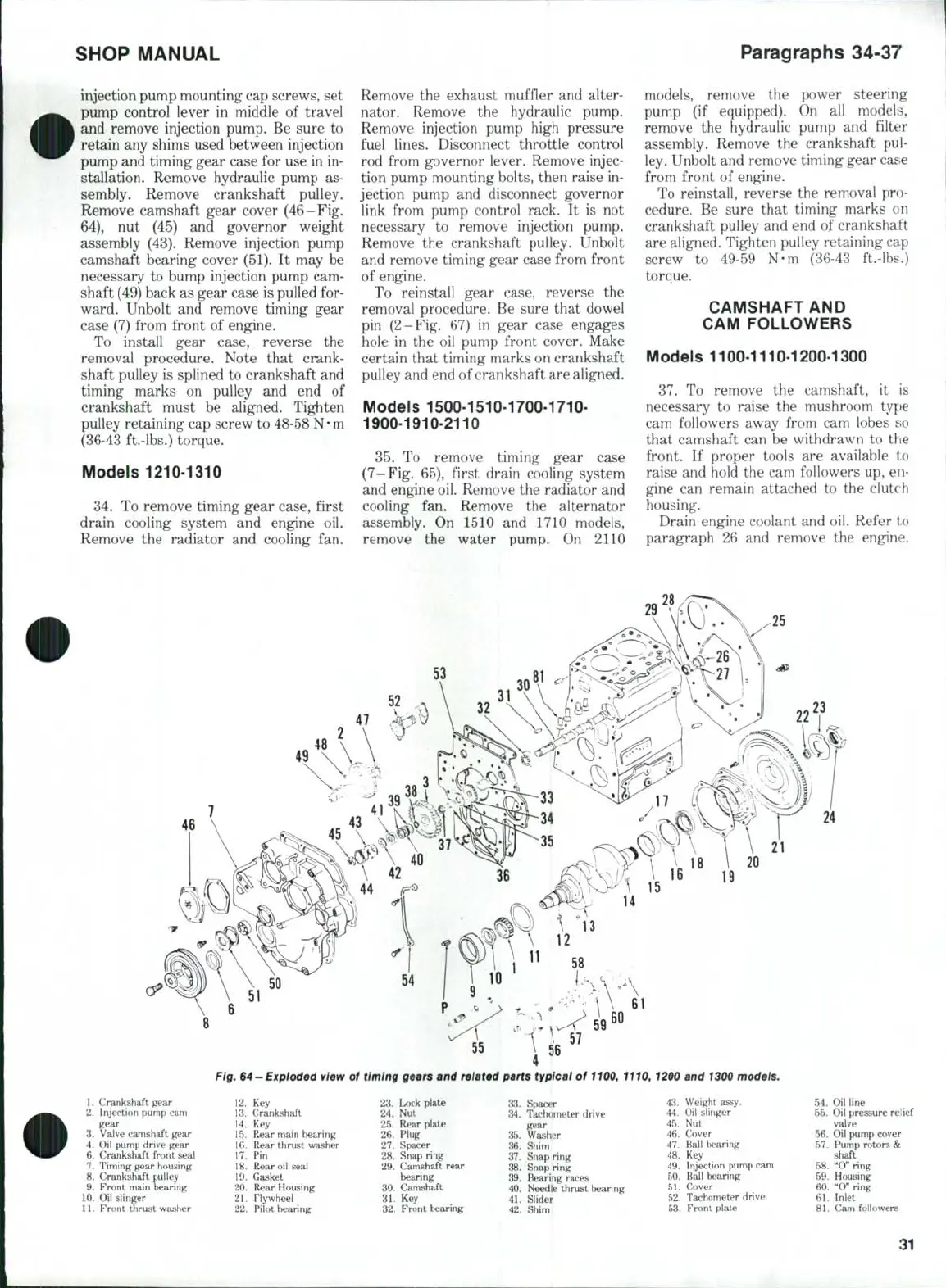
Fig. 64-Exptoded view of timing gears and related parts typical of 1100, 1110, 1200 and 1300 models.
1.
Crankshaft gear
2.
Injection pump cam
gear
3.
Valve camshaft gear
4.
Oil pump drive gear
6. Crankshaft front seal
7.
Timing gear housing
8. Crankshaft pulley
9. Front main bearing
10.
Oil slinger
11.
Front thrust washer
12.
Key
13.
Crankshaft
14.
Key
15.
Rear main bearing
16.
Rear thrust washer
17.
Pin
18.
Rear oil seal
19.
Gasket
20.
Rear Housing
21.
Flywheel
22.
F'ilot bearing
23.
24.
25.
26.
27.
28.
29.
30.
31.
32.
Lock plate
Nut
Rear plate
Plug
Spacer
Snap ring
Camshaft rear
bearing
Camshaft
Key
Fn)nt bearing
33.
Spacer
34.
Tachometer drive
gear
35.
Washer
36.
Shim
37.
Snap ring
38.
Snap ring
39.
Bearing races
40.
Needle thrust bearing
41.
Slider
42.
Shim
43.
Weight assy.
44.
Oil slinger
45.
Nut
46.
Cover
47.
Ball bearing
48.
Key
49.
Injection pump cam
50.
Ball Itwaring
51.
Cover
52.
Tachometer drive
53.
Front plate
24
54.
Oil line
55.
Oil pressure relief
valve
56.
Oil pump cover
57.
Pump rotors &
shaft
58.
"0" ring
59.
Housing
60.
"0" ring
61.
Inlet
81.
Cam followers
31