Paragraph
37
(Cont.)
FORD
63
70
V^'
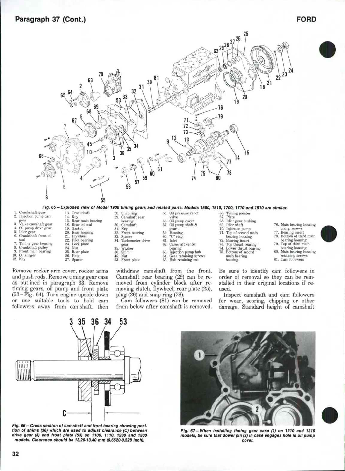
Fig.
65
1.
Crankshaft gear
2.
Injection pump cam
gear
3.
Valve camshaft gear
4.
Oil pump drive gear
5.
Idler gear
6. Crankshaft front oil
seal
7.
Timing gear housing
8. Crankshaft pulley
9. Front main bearing
10.
Oil slinger
12.
Key
-Exploded view of Model 1900 timing gears and related parts. Models 1500, 1510, 1700, 1710 and 1910 are similar.
13.
Crankshaft
14.
Key
15.
Rear main bearing
18.
Rear oil seal
19.
Gasket
20.
Rear housing
21.
Flywheel
22.
Pilot bearing
23.
Lock plate
24.
Nut
25.
Rear plate
26.
Plug
27.
Spacer
Remove rocker arm cover, rocker arms
and push rods. Remove timing gear case
as outlined
in
paragraph
33.
Remove
timing gears,
oil
pump
and
front plate
(53-Fig. 64). Turn engine upside down
or
use
suitable tools
to
hold
cam
followers away from camshaft, then
28.
29.
30.
31.
32.
33.
34.
35.
36.
45.
53.
Snap ring
Camshaft rear
bearing
Camshaft
Key
Front bearing
Spacer
Tachometer drive
gear
Washer
Shim
Nut
Front plate
55.
Oil pressure rehet
valve
56.
Oil pump cover
57.
Oil pump shaft &
gears
59.
Housing
60.
"0" ring
61.
Inlet
62.
Camshaft center
bearing
63.
Injection pump hub
64.
Gear retaining screws
65.
Hub retaining nut
66.
67.
68.
69.
70.
71.
72.
73.
74.
75.
Timing pointer
Plate
Idler gear bushing
Idler shaft
Injection pump
Top
of
second main
bearing housing
Bearing insert
Top thrust bearing
Lower thrust bearing
Bottom
of
second
main bearing
housing
withdraw camshaft from
the
front.
Camshaft rear bearing (29)
can be re-
moved from cylinder block after
re-
moving clutch, flywheel, rear plate (25),
plug (26) and snap ring (28).
Cam followers
(81) can be
removed
from below after camshaft
is
removed.
76.
Main bearing housing
clamp screws
77.
Bearing insert
78.
Bottom
of
third main
bearing housing
79.
Top
of
third niain
bearing housing
80.
Main bearing housing
retaining screws
81.
Cam followers
Be sure
to
identify
cam
followers
in
order
of
removal
so
they
can be
rein-
stalled
in
their original locations
if re-
used.
Inspect camshaft
and cam
followers
for wear, scoring, chipping
or
other
damage. Standard height
of
camshaft
3
35 36 34 53
Fig.
66
—
Cross section of camshaft and front bearing showing posi-
tion of shims (36) which are used to adjust clearance (C) between
drive gear (3) and front plate (53) on 1100, 1110, 1200 and 1300
models. Clearance should be
13.20-13.40
mm
(0.6520-0.526
inch).
Fig. 67-When installing timing gear case (1) on 1210 and 1310
models, be sure that dowel pin
(2) In
case engages hole
In
oil pump
32
 Loading...

