SHOP MANUAL
Paragraphs 38-39
lobes
is
36.02-36.07 mm (1.418-1.420
in-
ches)
and
minimum allowable height
is
5.65 mm (1.404 inches). Camshaft run-
ut should
not
exceed
0.10 mm
(0.004
inch).
Cam followers should be renewed
if camshaft
is
renewed.
When installing camshaft, measure
distance
(C
-
Fig.
66) between
the
front
face
of
engine front plate (53)
and
rear
face
of
camshaft gear
(3).
If
clearance
is
nt 13.2-13.4 mm (0.520-0.528 inch),
add
or remove shims (36)
as
required before
making final assembly.
Turn crankshaft and camshaft until in-
jection pump gear can
be
installed with
both sets
of
timing marks aligned
as
shown
in
Fig.
57.
17
16
Models 1210-1310
38,
The
camshaft
can be
removed
without separating engine from trans-
mission. However,
if
camshaft rear
bearing (2-Fig.
68) is to be
renewed,
engine must
be
removed from tractor
and clutch, flywheel
and
rear plate
removed.
To remove camshaft
(3),
remove radia-
tor, timing gear case
and
fuel injection
pump. Remove cylinder head, then lift
barrel type
cam
followers
out top of
cylinder block.
Be
sure
to
identify posi-
tion
of
each cam follower so they can be
reinstalled in original positions if reused.
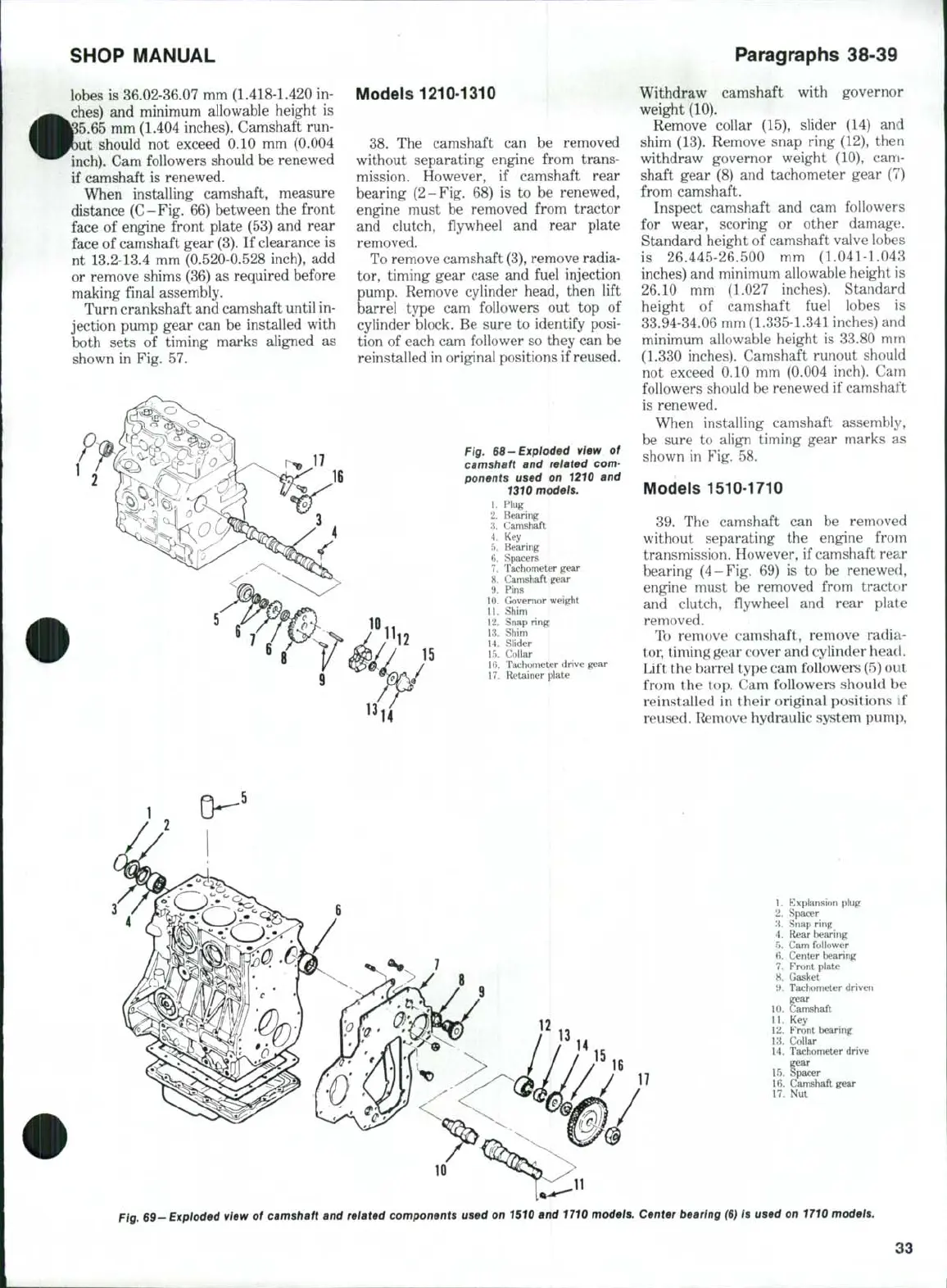
Fig. 66-Exploded view of
camshaft and reiated com-
ponents used on 1210 and
1310 models.
1.
Plug
2.
Bearing
3.
Camshaft
4.
Key
5.
Bearing
6. Spacers
7.
Tachometer gear
8. Camshaft gear
9. Pins
10.
Governor weight
11.
Shim
12.
Snap ring
13.
Shim
14.
Slider
15.
Collar
16.
Tachometer drive gear
17.
Retainer plate
Withdraw camshaft with governor
weight (10).
Remove collar
(15),
slider
(14) and
shim (13). Remove snap ring (12), then
withdraw governor weight
(10), cam-
shaft gear
(8) and
tachometer gear
(7)
from camshaft.
Inspect camshaft
and cam
followers
for wear, scoring
or
other damage;.
Standard height
of
camshaft valve lobes
is 26.445-26.500
mm
(1.04M.043
inches) and minimum allowable height
is
26.10
mm
(1.027 inches). Standard
height
of
camshaft fuel lobes
is
33.94-34.06 mm (1.335-1.341 inches) and
minimum allowable height
is
33.80
mm
(1.330 inches). Camshaft runout should
not exceed
0.10 mm
(0.004 inch).
Cam
followers should be renewed
if
camshaft
is renewed.
When installing camshaft assembly,
be sure
to
align timing gear marks
as
shown
in
Fig.
58.
Models 1510-1710
39.
The
camshaft
can be
removed
without separating
the
engine from
transmission. However, if camshaft rear
bearing (4-Fig.
69) is to be
renewed,
engine must
be
removed from tractor
and clutch, flywheel
and
rear plate
removed.
To remove camshaft, remove radia-
tor, timing gear cover and cylinder head.
Lift the barrel type cam followers (5) out
from
the
top. Cam followers should
be
reinstalled
in
their original positions
if
reused. Remove hydraulic system pump.
1.
Explansion plug
2.
Spacer
'A.
Snap ring
4.
Rear bearing
5.
Cam follower
H. Center bearing
7.
Front plate
8. Gasket
9. Tachometer driven
10.
Camshaft
11.
Key
12.
Front bearing
13.
Collar
14.
Tachometer drive
gear
15.
Spacer
16.
Camshaft gear
17.
Nut
11
Fig. 69-Expioded view of camshaft and related components used on 1510 and 1710 models. Center bearing
(6)
Is used on 1710 modeis.
33
 Loading...

