Paragraphs 40-42
FORD
injection pump and drive gear
(1
- Fig.
70),
idler gear (3) and shaft, camshaft
gear
(4),
engine oil pump
(5),
oil pressure
relief valve (6) and oil transfer tube (7).
Remove engine front plate, then with-
draw camshaft.
Inspect camshaft and cam followers
for wear, scoring or other damage.
Standard height of camshaft valve lobes
is 36.02-36.07 mm (1.418-1.420 inches)
and minimum allowable height is 35.5
mm (1.398 inches). Camshaft runout
should not exceed 0.10 mm (0.004 inch).
Cam followers should be renewed if
camshaft is renewed.
To reinstall camshaft, reverse the
removal procedure. Align timing gear
marks as outined in paragraph 32.
Models 1500-1700-1900-1910-2110
40.
To remove camshaft, it is
necessary to move the mushroom type
cam followers away from the cam lobes
so camshaft can be withdrawn from the
front. This is normally accomplished by
turning the engine upside down to allow
cam followers to fall away from the cam-
shaft. However, if suitable tools are
available to raise and hold the cam fol-
lowers up, the camshaft can be removed
without removing engine from the trac-
tor.
Drain engine coolant and oil. Remove
engine as outlined in paragraph 26.
Remove rocker arm cover, rocker arms
and supports, identifying the rocker
assemblies so they can be reinstalled in
their original position. Remove timing
gear front cover, injection pump and
drive gear, camshaft gear, engine oil
pump and drive gear, oil transfer tube
and tachometer driven gear. Remove
engine front plate, then withdraw cam-
shaft and front bearing from cylinder
block. Remove clutch, flywheel and
engine rear plate for access to camshaft
rear bearing. Cam followers and cam-
shaft center needle bearing (1900, 1910
and 2110 models) are removed from
below after removing engine oil pan and
balancer assembly (2110 models).
Inspect camshaft and cam followers
for wear, scoring or other damage and
renew if necessary. Standard height of
camshaft valve lobes on 1500, 1700 and
1900 models is 38,017-38.072 mm
(1.497-1.500 inches) and minimum
allowable height is 37.50 mm (1.476
inches). Standard height of camshaft
valve lobes on 1910 and 2110 models is
88,06-38.07 mm (1.498-1.500 inches) and
minimum allowable height is 37,65 mm
(1,482 inches). Camshaft runout should
not exceed 0,10 mm (0.004 inch) on all
models. Cam followers should be re-
newed if camshaft is renewed.
Lubricate camshaft, bearings and cam
followers prior to installation. Align tim-
ing gear marks as outlined in paragraph
32.
ROD AND PISTON UNITS
All Models
41.
Connecting rod and piston units
can be removed from above after remov-
ing cylinder head, engine oil pan and oil
pump pickup tube. On 2110 models, en-
gine balancer assembly and idler gear
must also be removed. On all models, be
sure that carbon deposits and wear
ridge (if present) are removed from top
of cylinder before pushing piston out.
Remove connecting rod cap, then push
piston and rod assembly out top of block.
Note that the piston pin is a transi-
tional fit in piston. Heating the piston in
hot water will facilitate removal and in-
stallation of piston pin. Be sure to keep
piston, connecting rod and cap together
and identified for each cylinder so they
Fig. 70- View of engine tim-
ing gears on Model 1710.
1.
Injection pump drive
gear
2.
Coupling
3.
Idler gear
4.
Camshaft gear
5'.
Oil pump
6. Oil pressure relief
valve
7.
Oil transfer tube
can be reinstalled in their original loca-
tions.
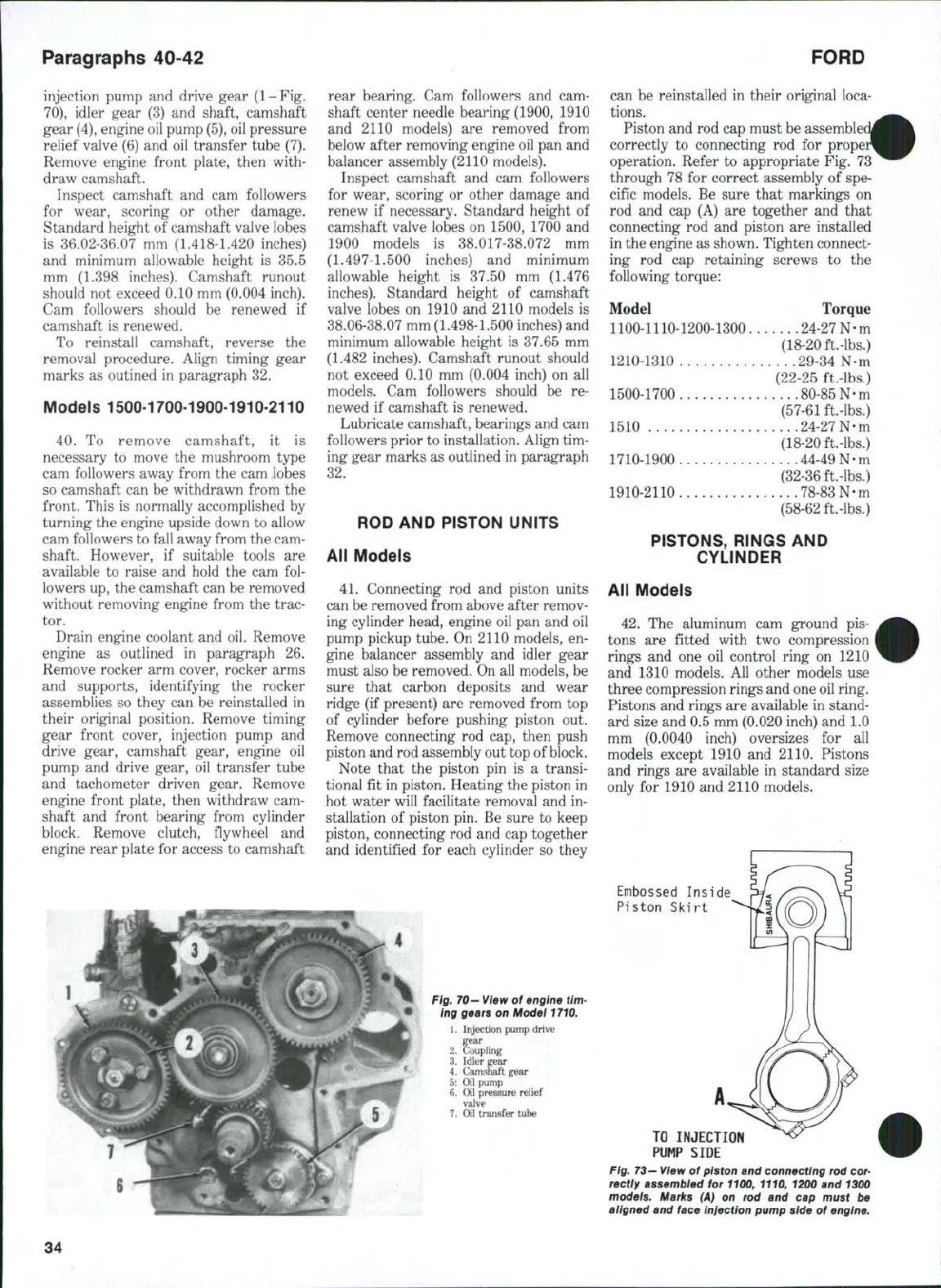
Piston and rod cap must be
correctly to connecting rod for
operation. Refer to appropriate Fig. 73
through 78 for correct assembly of spe-
cific models. Be sure that markings on
rod and cap (A) are together and that
connecting rod and piston are installed
in the engine as shown. Tighten connect-
ing rod cap retaining screws to the
following torque:
Model Torque
1100-1110-1200-1300 24-27 N-m
(18-20 ft.-lbs.)
1210-1310 29-34 N - m
(22-25 ft.-lbs.)
1500-1700 80 -8 5N- m
(57-61 ft-lbs,)
1510 24 -2 7N- m
(18-20 ft.-lbs.)
1710-1900 44-49 N - m
(32-36 ft.-lbs.)
1910-2110 78 -83 N-m
(58-62
ft-lbs.)
PISTONS, RINGS AND
CYLINDER
All Models
42,
The aluminum cam ground pis-
tons are fitted with two compression
rings and one oil control ring on 1210
and 1310 models. All other models use
three compression rings and one oil ring.
Pistons and rings are available in stand-
ard size and 0.5 mm (0.020 inch) and 1,0
mm (0,0040 inch) oversizes for all
models except 1910 and 2110. Pistons
and rings are available in standard size
only for 1910 and 2110 models.
Embossed Inside
Piston Skirt
TO INJECTION
PUMP SIDE
Fig.
73—
View of piston and connecting rod
cor-
rectly assembled for 1100, 1110, 1200 and 1300
models. Marks (A) on rod and cap must be
aligned and face injection pump side of engine.
34
 Loading...

