SHOP MANUAL
Paragraph 42 (Cont.)
Check piston ring grooves
for
wear
using
new
rings
and a
feeler gage
to
measure side clearance
as
shown
in Fig.
'80.
Renew piston
if
clearance exceeds
0,25
mm
(0,010 inch)
for
compression
rings
and 0.15 mm
(0,006 inch)
for oil
control ring. Check pistons
for
wear,
scratches
or
scoring
and
renew
if
neces-
sary.
Check cylinder bore
for
wear, scoring
or other damage.
On all
models except
1910
and
2110, cylinders
can be
rebored
for installation
of
0,5 mm (0.020 inch)
or
1.0 mm
(0.040 inch) oversize pistons.
On 1910
and
2110 models, renewable,
wet type cylinder sleeves
are
used.
The
cylinder sleeves can
be
driven
out
top of
cylinder block
or
removed using
a
Embossed Inside
Piston Skirt
TO EXHAUST
MANIFOLD SIDE
Fig.
74 —
View
of
piston
and
connecting rod
cor-
rectly assembled
for 1210 and 1310
models.
Marks
(A) on rod and cap
must
be
aligned
and
face away from iniection pump side
of
engine.
suitable puller.
Be
sure
to
thoroughly
clean cylinder block
to
remove rust
and
other deposits before installing
new
sleeve. Lubricate
"0"
ring seals, then
carefully push sleeves into cylinder block
until fully seated. Check protrusion
of
sleeve above face
of
cylinder block using
a straightedge
and
feeler gage
as
shown
in Fig, 81. Flange protrusion (A) should
be 0,0-0.1
mm
(0.0-0.004 inch)
and lip
protrusion
(B)
should
be
0.90-1.05
mm
(0.036-0,041 inch).
If
protrusion
is ex-
cessive, check
for
foreign material
in
cylinder block counterbore.
If
sleeve
flange dimension
is
correct,
but lip pro-
trusion is excessive, surface grind sleeve
lip
to
obtain correct height.
To I njecti on
Pump Side
Embossed Inside
Piston S k ir t
TO INJECTION
PUMP SIDE
Fig. 76—View
of
piston and connecting rod
cor-
rectly assembled
for 1510 and 1710
models.
Marks
(A) on rod and cap
must
be
aligned
and
face iniection pump side
of
engine.
Fig. 75—View
of
piston
and
connecting rod cor-
rectly assembled
for 1500 and 1700
models.
Marks
(A) on rod and cap
must
be
aligned
and
face camshaft side
of
engine.
Fig.
77—
View
of
piston and connecting rod
cor-
rectly assembled
for
1900 models. Marks (A)
on
rod
and cap
must
be
aligned
and
face Iniection
pump side
of
engine.
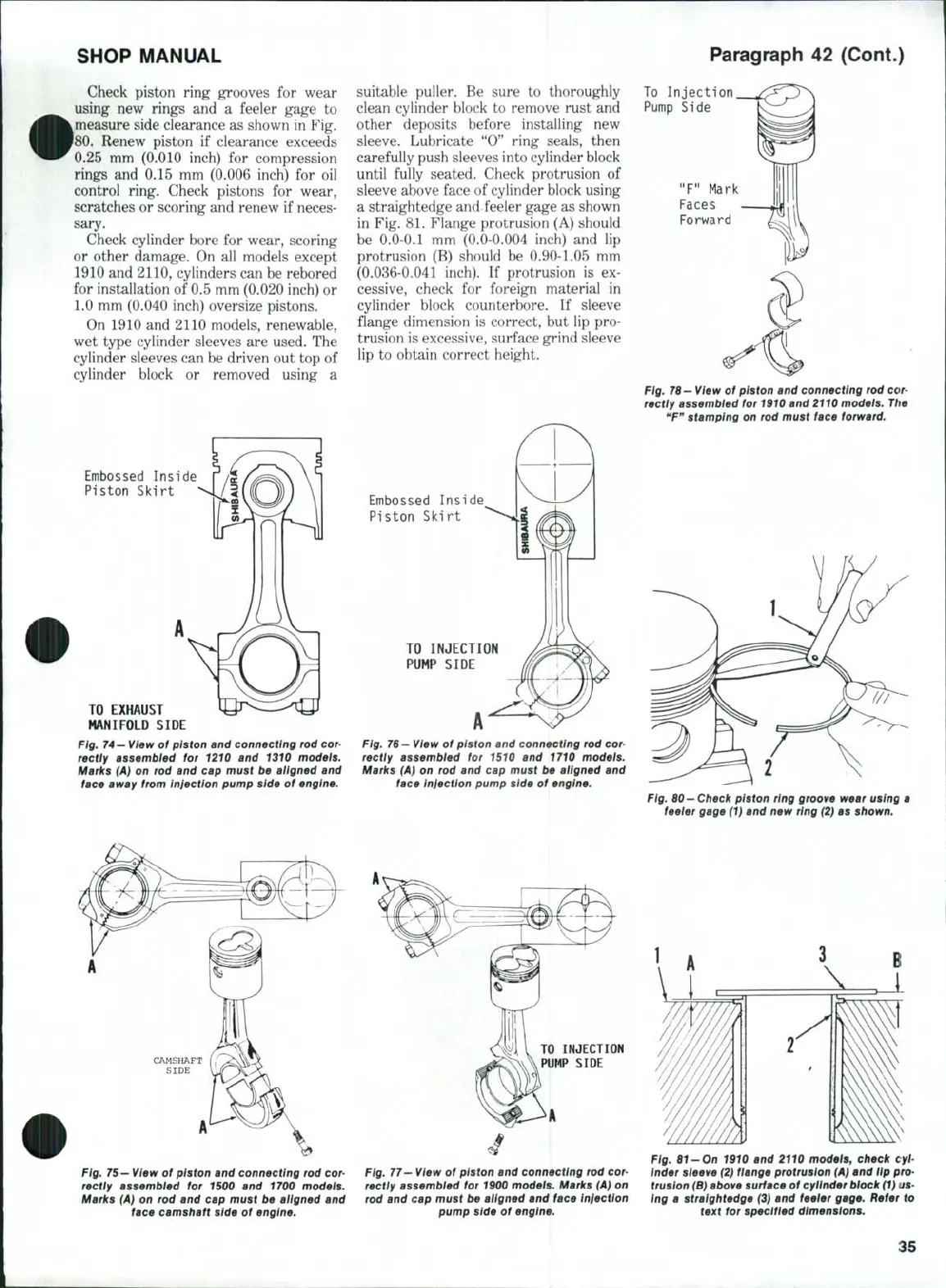
Fig. 76—View
of
piston
and
connecting rod cor-
rectly assembled
for
1910 and 2110 models.
The
"F"
stamping
on
rod must face forward.
Fig. 60— Check piston ring groove wear using
a
feeler gage (1)
and new
ring (2)
as
shown.
Fig.
61-On 1910 and 2110
models, check
cyl-
inder sleeve (2) flange protrusion (A) and
Up
pro-
trusion (B) above surface
of
cyiinder block (1)
us-
ing
a
straightedge
(3) and
feeler gage. Refer
to
text
for
specified dimensions.
35