SHOP MANUAL
Paragraph 46
front) holder on 1210 and 1310 models
has an identification mark (3-Fig. 92)
it to ensure correct assembly,
'ighten bearing holder cap screws to a
torque of 25-29 N-m (18-22 ft.-lbs,) on
1210 and 1310 models; 48-53 N-m (36-39
ft.-lbs,) on 1510 and 1710 models; 70-80
N-m (51-59 ft.-lbs,) on 1900, 1910 and
2110 models. Insert crankshaft
assembly into cylinder block and front
main bearing. Install bearing holder re-
taining bolts and tighten to a torque of
25-29 N-m (18-22 ft.-lbs,) on 1210 and
1310 models and 70-80 N-m (51-59
ft,-lbs.) on all other models.
Measure crankshaft end play using a
dial indicator. If end play exceeds 0,70
mm (0,028 inch), renew thrust washers.
Install oil seal and rear plate on 1210
and 1310 models and tighten retaining
cap screws to 27-33 N-m (20-24 ft.-lbs.)
torque. On all other models, install rear
cover with main bearing and new oil
seal. Tighten cover retaining cap screws
evenly to 46-54 N-m (34-40 ft.-lbs.)
torque.
On all models, complete installation by
reversing removal procedure. Be sure
timing gear marks are correctly aligned
as outlined in paragraph 32. On 2110
models, refer to paragraph 47 for timing
and installation of engine balancer. On
all models, be sure timing marks on
crankshaft pulley and end of crankshaft
are aligned.
FLYWHEEL
All Models
46.
To remove flywheel, first split
tractor between engine and transmis-
sion as outlined in paragraph 101 and
remove clutch assembly. On 1210, 1310
and 1510 models, remove cap screws
and retainer plate attaching flywheel to
crankshaft, then remove the flywheel.
On all other models, loosen the flywheel
retaining nut, but do not remove the nut
from the crankshaft. While prying out-
ward on flywheel, tap end of crankshaft
with a brass drift and hammer to loosen
flywheel from the tapered end of crank-
shaft. Remove retaining nut and fly-
wheel.
Inspect flywheel and ring gear for ex-
cessive wear or other damage and renew
if necessary. When installing a new ring
gear, heat the gear evenly to a temp-
erature of 120°-150° C (245°-300° F),
Install the heated gear quickly making
sure it is seated against shoulder of
flywheel.
Install flywheel on crankshaft and
tighten retaining cap screws to 56-69
N-m
(41-51
ft.-lbs.) torque on 1210, 1310
and 1510 models. On all other models,
tighten retaining nut to 343-441 N*m
(253-325 ft.-lbs.) torque.
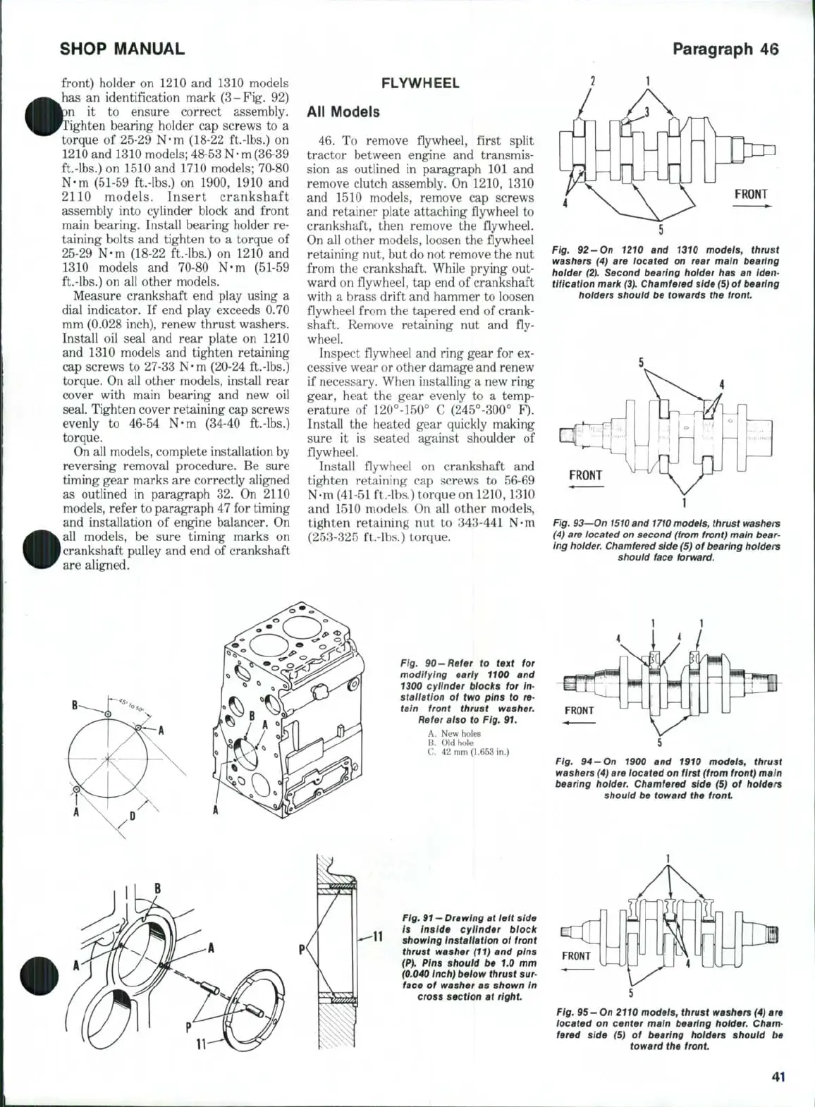
Fig, 92-On 1210 and 1310 modeis, thrust
washers (4) are located on rear main bearing
hoider (2), Second bearing holder has an Iden-
tification mark
(3).
Chamfered side (5) of bearing
holders should be towards the front
Fig. 93'-On
1510
and
1710
models,
thrust
washers
(4) are located on second (from front) main
bear-
ing
holder.
Chamfered side (5) of bearing
holdei's
should face forward.
Fig. 90-Refer to text for
modifying early 1100 and
1300 cylinder blocks for In-
stallation of two pins to re-
tain front thrust washer.
Refer aiso to Fig. 91.
A. New holes
B.
Old hole
C. 42 mm (1.653 in.)
FRONT
Fig. 94-On 1900 and 1910 models, thrust
washers (4) are located on first (from front) main
bearing
hoider.
Chamfered side (5) of holders
should be toward the front
Fig.
91
- Drawing at left side
Is Inside cylinder block
showing instaiiation of front
thrust washer (11) and pins
(P).
Pins shouid be 1.0 mm
(0.040 inch) below thrust
sur-
face of washer as shown In
cross section at
right.
FRONT
Fig,
95 —On
2110 models, thrust washers (4) are
located on center main bearing
holder.
Cham-
fered side (5) of bearing holders should be
toward the front
41
 Loading...

