Paragraph 45 (Cont.) FORD
Crankpin Journal Diameter
Standard 59.95-59,97 mm
(2.3602-2.3610 in.)
Crankpin Bearing Clearance
Desired 0.040-0.104 mm
(0,0016-0,0040 in,)
Wear Limit 0.20 mm
(0,008 in,)
Taper and Out-of-Round,
All Journals
Wear Limit 0.05 mm
(0,002 in.)
End Play
Desired 0.10-0.45 mm
(0.004-0,018 in,)
Wear Limit 0,70 mm
(0,028 in,)
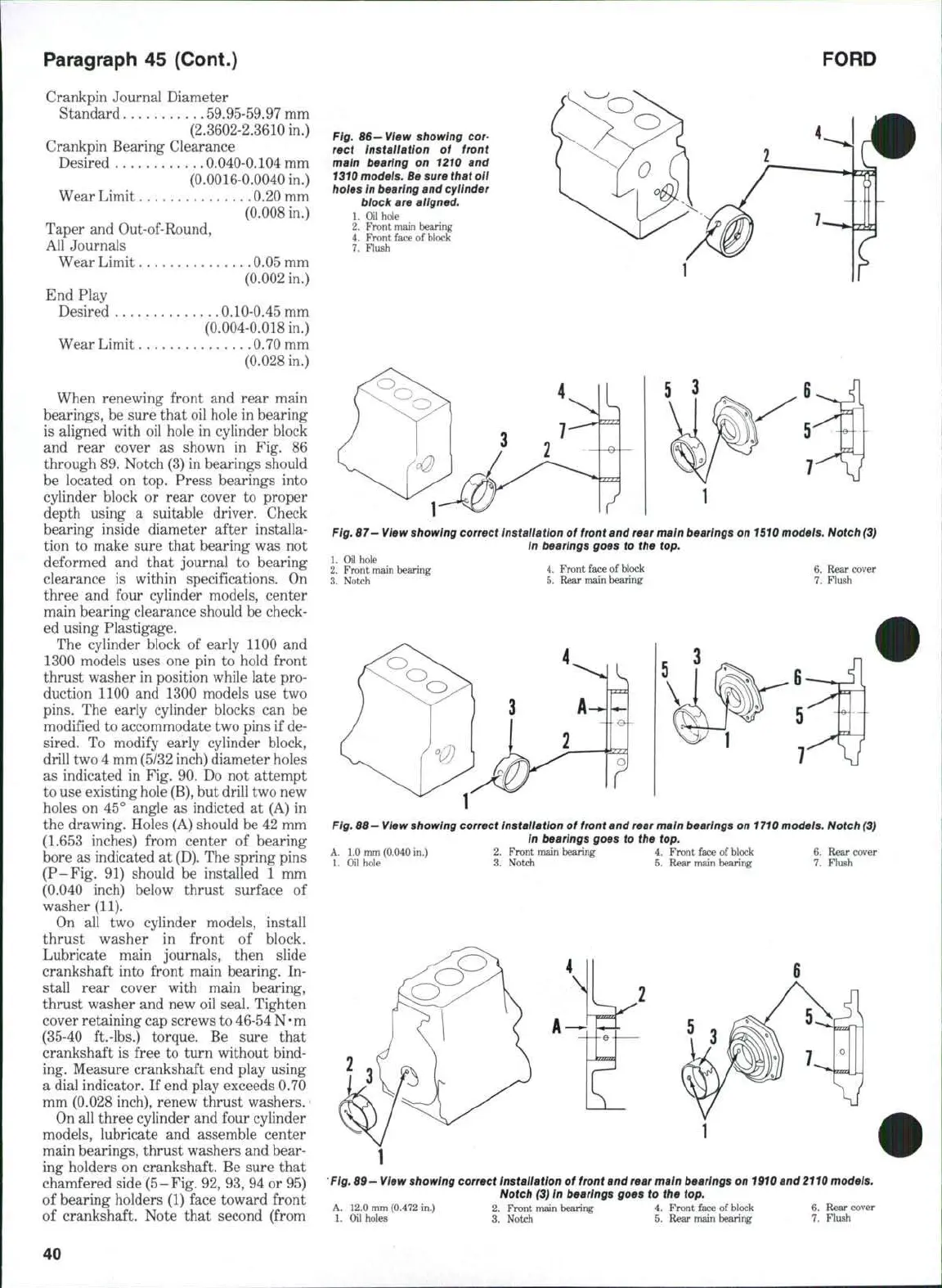
When renewing front and rear main
bearings, be sure that oil hole in bearing
is aligned with oil hole in cylinder block
and rear cover as shown in Fig, 86
through 89. Notch (3) in bearings should
be located on top. Press bearings into
cylinder block or rear cover to proper
depth using a suitable driver. Check
bearing inside diameter after installa-
tion to make sure that bearing was not
deformed and that journal to bearing
clearance is within specifications. On
three and four cylinder models, center
main bearing clearance should be check-
ed using Plastigage.
The cylinder block of early 1100 and
1300 models uses one pin to hold front
thrust washer in position while late pro-
duction 1100 and 1300 models use two
pins.
The early cylinder blocks can be
modified to accommodate two pins if de-
sired. To modify early cylinder block,
drill two 4 mm (5/32 inch) diameter holes
as indicated in Fig. 90. Do not attempt
to use existing hole
(B),
but drill two new
holes on 45° angle as indicted at (A) in
the drawing. Holes (A) should be 42 mm
(1.653 inches) from center of bearing
bore as indicated at
(D),
The spring pins
(P-Fig, 91) should be installed 1 mm
(0.040 inch) below thrust surface of
washer (11).
On all two cylinder models, install
thrust washer in front of block.
Lubricate main journals, then slide
crankshaft into front main bearing. In-
stall rear cover with main bearing,
thrust washer and new oil seal. Tighten
cover retaining cap screws to 46-54
N • m
(35-40 ft.-lbs.) torque. Be sure that
crankshaft is free to turn without bind-
ing. Measure crankshaft end play using
a dial indicator. If end play exceeds 0,70
mm (0.028 inch), renew thrust washers.
On all three cylinder and four cylinder
models, lubricate and assemble center
main bearings, thrust washers and bear-
ing holders on crankshaft. Be sure that
chamfered side (5-Fig. 92, 93, 94 or 95)
of bearing holders (1) face toward front
of crankshaft. Note that second (from
Fig,
66—
View showing cor-
rect Installation of front
main bearing on 1210 and
1310
modeis. Be sure that oil
holes in bearing and cylinder
biock are aligned,
1.
Oil hoie
2,
Front main bearing
4.
Front face of block
7.
Flush
L
Fig,
67—
View
showing correct Installation of
front
and
rear
main bearings on
1510
models. Notch
(3)
in bearings goes to the top.
1.
Oil hole
2.
Front main bearing
3.
Notch
4.
Front face of block
5.
Rear main bearing
6. Rear cover
7.
Flush
iA^^
Fig,
86-
View
showing correct Installation of
front
and
rear main
bearings on
1710
models. Notch
(3)
In
bearings goes to the top.
A. 1.0 mm (0.040 in.) 2. Front main bearing 4. Front face of block 6. Rear cover
1.
Oil hole 3. Notch 5. Rear main bearing 7. Flush
Fig.
69-
View
showing correct Installation of
front
and
rear
main bearings on
1910
and
2110
models.
Notch
(3) In
bearings goes to the top,
A. 12.0 mm (0.472 in.) 2. Front main bearing 4. Front face of block 6. Rear cover
1.
Oil holes 3. Notch 5. Rear main bearing 7. Flush
40
 Loading...

