Paragraphs 57-58
FORD
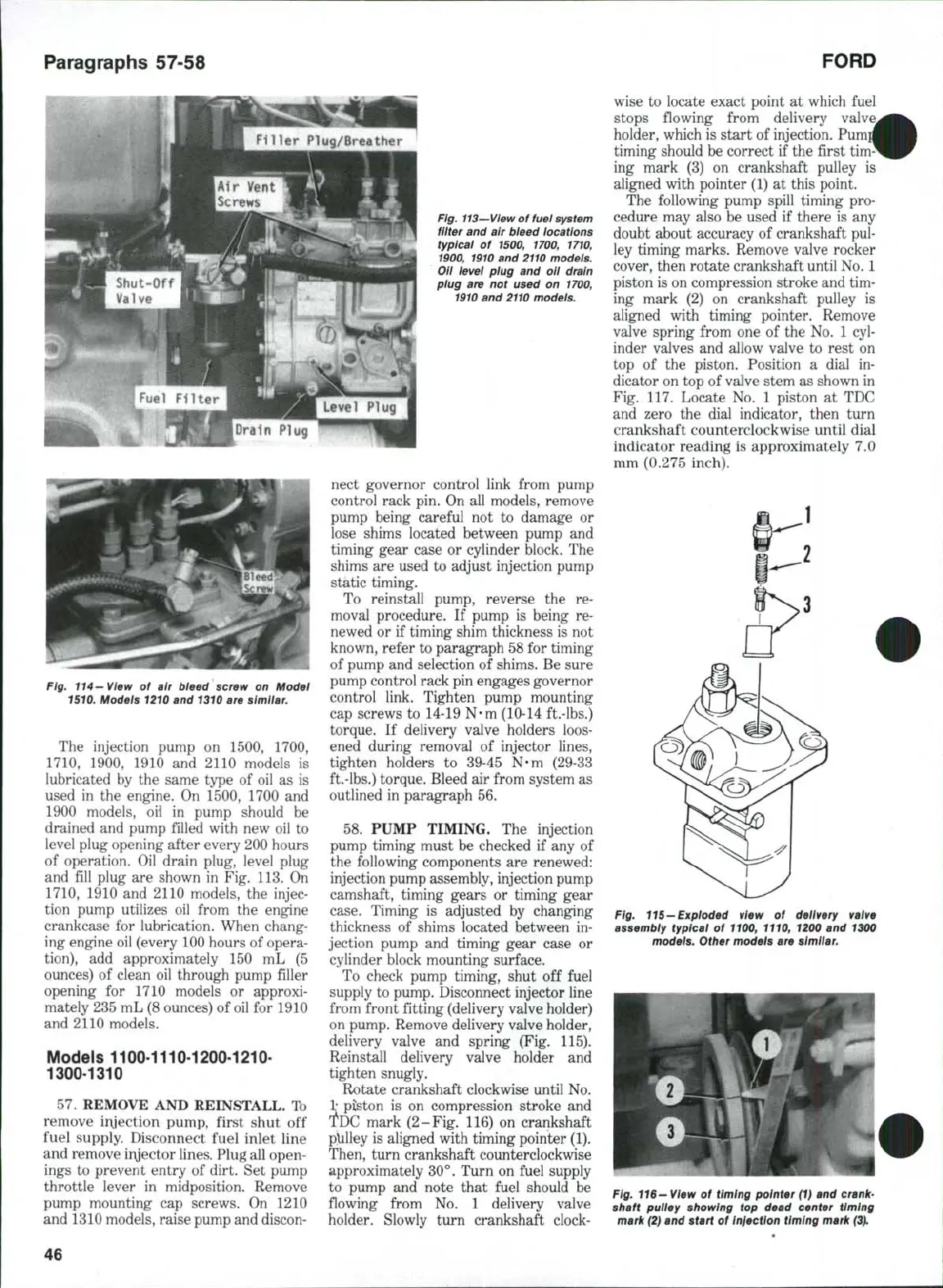
Fig.
113—View
of fuel system
filter and air bleed locations
typical of 1500, 1700, 1710,
1900,
1910
and
2110
models.
Oil level plug and oil drain
plug are not used on 1700,
1910
and
2110
models.
Fig. 114-View of air bleed screw on Model
1510, Models 1210 and 1310 are simitar.
The injection pump on 1500, 1700,
1710,
1900, 1910 and 2110 models is
lubricated by the same type of oil as is
used in the engine. On 1500, 1700 and
1900 models, oil in pump should be
drained and pump filled with new oil to
level plug opening after every 200 hours
of operation. Oil drain plug, level plug
and fill plug are shown in Fig. 113. On
1710,
1910 and 2110 models, the injec-
tion pump utilizes oil from the engine
crankcase for lubrication. When chang-
ing engine oil (every 100 hours of opera-
tion),
add approximately 150 mL (5
ounces) of clean oil through pump filler
opening for 1710 models or approxi-
mately 235 mL (8 ounces) of
oil
for 1910
and 2110 models.
Models 1100-1110-1200-1210-
1300-1310
57.
REMOVE AND REINSTALL. To
remove iryection pump, first shut off
fuel supply. Disconnect fuel inlet line
and remove iryector
lines.
Plug all open-
ings to prevent entry of dirt. Set pump
throttle lever in midposition. Remove
pump mounting cap screws. On 1210
and 1310 models, raise pump and discon-
nect governor control link from pump
control rack pin. On all models, remove
pump being careful not to damage or
lose shims located between pump and
timing gear case or cylinder block. The
shims are used to adjust injection pump
static timing.
To reinstall pump, reverse the re-
moval procedure. If pump is being re-
newed or if timing shim thickness is not
known, refer to paragraph 58 for timing
of pump and selection of shims. Be sure
pump control rack pin engages governor
control link. Tighten pump mounting
cap screws to 14-19 N-m (10-14 ft.-Ibs.)
torque. If delivery valve holders loos-
ened during removal of injector lines,
tighten holders to 39-45 N*m (29-33
ft,-lbs,) torque. Bleed air from system as
outlined in paragraph 56,
58,
PUMP TIMING. The injection
pump timing must be checked if any of
the following components are renewed:
injection pump assembly, injection pump
camshaft, timing gears or timing gear
case.
Timing is adjusted by changing
thickness of shims located between in-
jection pump and timing gear case or
cylinder block mounting surface.
To check pump timing, shut off fuel
supply to pump. Disconnect injector line
from front fitting (delivery valve holder)
on pump. Remove delivery valve holder,
delivery valve and spring (Fig. 115),
Reinstall delivery valve holder and
tighten snugly.
Rotate crankshaft clockwise until No.
V piston is on compression stroke and
tDC mark (2-Fig, 116) on crankshaft
plilley is aligned with timing pointer (1).
Then, turn crankshaft counterclockwise
approximately 30°, Turn on fuel supply
to pump and note that fuel should be
flowing from No. 1 delivery valve
holder. Slowly turn crankshaft clock-
wise to locate exact point at which fuel
stops flowing from delivery valve,
holder, which is start of injection.
timing should be correct if the first
ing mark (3) on crankshaft pulley is
aligned with pointer (1) at this point.
The following pump spill timing pro-
cedure may also be used if there is any
doubt about accuracy of crankshaft pul-
ley timing marks. Remove valve rocker
cover, then rotate crankshaft until No. 1
piston is on compression stroke and tim-
ing mark (2) on crankshaft pulley is
aligned with timing pointer. Remove
valve spring from one of the No. 1 cyl-
inder valves and allow valve to rest on
top of the piston. Position a dial in-
dicator on top of valve stem as shown in
Fig. 117. Locate No. 1 piston at TDC
and zero the dial indicator, then turn
crankshaft counterclockwise until dial
indicator reading is approximately 7.0
mm (0.275 inch).
11 i.U^l
valve^^^
;t tim^^^r
Fig.
115 —Exploded
view of delivery valve
assembly typical of 1100, 1110, 1200 and 1300
models. Other models are similar.
Fig. 116- View of timing pointer
(1)
and crank-
shaft pulley showing top dead center timing
mark
(2)
and start of Injection timing mark
(3).
46