SHOP MANUAL
Paragraphs 60-61
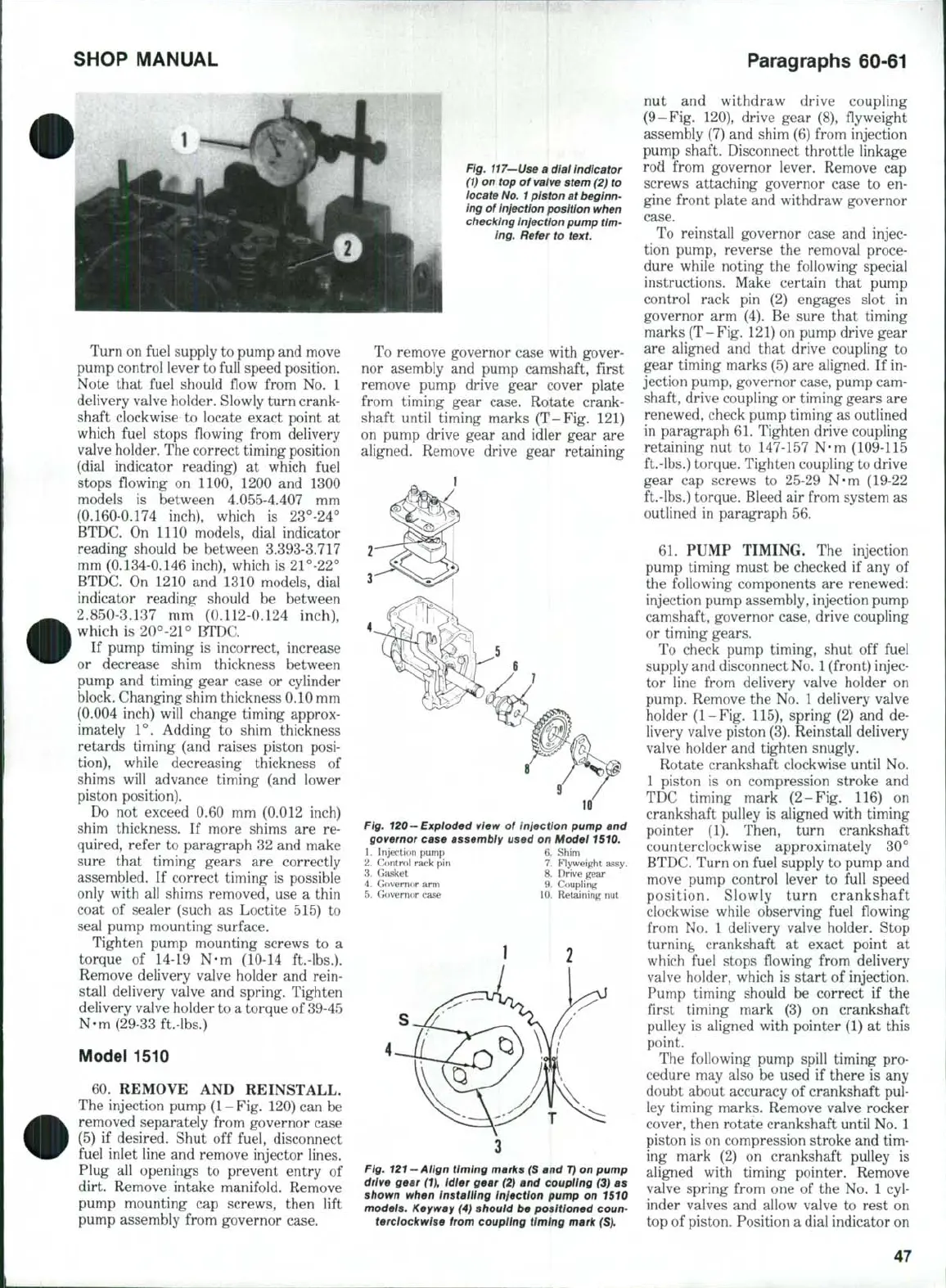
Fig.
117—Use
a dial indicator
(1)
on top of valve stem (2) to
locate
No.
1
piston at beginn-
ing of
injection
position when
ciiecklng
injection
pump tim-
ing. Refer to text.
Turn on fuel supply to pump and move
pump control lever to full speed position.
Note that fuel should fiow from No. 1
delivery valve holder. Slowly turn crank-
shaft clockwise to locate exact point at
which fuel stops flowing from delivery
valve holder. The correct timing position
(dial indicator reading) at which fuel
stops fiowing on 1100, 1200 and 1300
models is between 4.055-4,407 mm
(0,160-0.174 inch), which is 23°-24°
BTDC. On 1110 models, dial indicator
reading should be between 3.393-3.717
mm (0.134-0.146 inch), which is 21°-22°
BTDC. On 1210 and 1310 models, dial
indicator reading should be between
2.850-3.137 mm' (0.112-0.124 inch),
which is 20°-21° BTDC.
If pump timing is incorrect, increase
or decrease shim thickness between
pump and timing gear case or cylinder
block. Changing shim thickness 0.10 mm
(0.004 inch) will change timing approx-
imately 1°. Adding to shim thickness
retards timing (and raises piston posi-
tion),
while decreasing thickness of
shims will advance timing (and lower
piston position).
Do not exceed 0,60 mm (0,012 inch)
shim thickness. If more shims are re-
quired, refer to paragraph 32 and make
sure that timing gears are correctly
assembled. If correct timing is possible
only with all shims removed, use a thin
coat of sealer (such as Loctite 515) to
seal pump mounting surface.
Tighten pump mounting screws to a
torque of 14-19 N-m (10-14 ft.-lbs,).
Remove delivery valve holder and rein-
stall delivery valve and spring. Tighten
delivery valve holder to a torque of 39-45
N-m (29-33 ft,-lbs.)
Model 1510
60,
REMOVE AND REINSTALL.
The injection pump (1-Fig. 120) can be
removed separately from governor case
(5) if desired. Shut off fuel, disconnect
fuel inlet line and remove injector lines.
Plug all openings to prevent entry of
dirt. Remove intake manifold. Remove
pump mounting cap screws, then lift
pump assembly from governor case.
To remove governor case with gover-
nor asembly and pump camshaft, first
remove pump drive gear cover plate
from timing gear case. Rotate crank-
shaft until timing marks (T-Fig. 121)
on pump drive gear and idler gear are
aligned. Remove drive gear retaining
Fig, 120—Exploded view of iniection pump and
governor case assembly used on Model 1510.
1.
Injection pump 6. Shim
2.
Control rack pin 7. Flyweight assy.
3.
Gjisket 8. Drive gear
4.
Govermir arm 9. Coupling
5.
Governor case 10. Retaining nut
Fig.
121 —Align
timing marks (S and
T)
on pump
drive gear
(1),
Idler gear
(2)
and coupling (3) as
shown when Installing injection pump on 1510
models. Keyway
(4)
should be positioned coun-
terclockwise from coupling timing mark (S).
nut and withdraw drive coupling
(9-Fig. 120), drive gear (8), flyweight
assembly (7) and shim (6) from injection
pump shaft. Disconnect throttle linkage
rod from governor lever. Remove cap
screws attaching governor case to en-
gine front plate and withdraw governor
case.
To reinstall governor case and injec-
tion pump, reverse the removal proce-
dure while noting the following special
instructions. Make certain that pump
control rack pin (2) engages slot in
governor arm (4). Be sure that timing
marks (T-Fig, 121) on pump drive gear
are aligned and that drive coupling to
gear timing marks (5) are aligned. If in-
jection pump, governor case, pump cam-
shaft, drive coupling or timing gears are
renewed, check pump timing as outlined
in paragraph 61. Tighten drive coupling
retaining nut to 147-157 N-m (109-115
ft.-lbs.) torque. Tighten coupling to drive
gear cap screws to 25-29 N-m (19-22
ft.-lbs,) torque. Bleed air from system as
outlined in paragraph 56.
61,
PUMP TIMING. The injection
pump timing must be checked if any of
the following components are renewed:
injection pump assembly, injection pump
camshaft, governor case, drive coupling
or timing gears.
To check pump timing, shut off fuel
supply and disconnect
No,
1
(front) injec-
tor line from delivery valve holder on
pump. Remove the No. 1 delivery valve
holder (1-Fig. 115), spring (2) and de-
livery valve piston (3), Reinstall delivery
valve holder and tighten snugly.
Rotate crankshaft clockwise until No,
1 piston is on compression stroke and
TDC timing mark (2-Fig. 116) on
crankshaft pulley is aligned with timing
pointer (1). Then, turn crankshaft
counterclockwise approximately 30°
BTDC, Turn on fuel supply to pump and
move pump control lever to full speed
position. Slowly turn crankshaft
clockwise while observing fuel fiowing
from No. 1 delivery valve holder. Stop
turning crankshaft at exact point at
which fuel stops flowing from delivery
valve holder, which is start of injection.
Pump timing should be correct if the
first timing mark (3) on crankshaft
pulley is aligned with pointer (1) at this
point.
The following pump spill timing pro-
cedure may also be used if there is any
doubt about accuracy of crankshaft pul-
ley timing marks. Remove valve rocker
cover, then rotate crankshaft until No, 1
piston is on compression stroke and tim-
ing mark (2) on crankshaft pulley is
aligned with timing pointer. Remove
valve spring from one of the No. 1 cyl-
inder valves and allow valve to rest on
top of piston. Position a dial indicator on
47
 Loading...

