Paragraphs 62-63
FORD
top of valve stem as shown in Fig. 117,
Locate No.
1
piston at TDC and zero the
dial indicator, then turn crankshaft
counterclockwise until dial indicator
reading is approximately 7,0 mm (0.275
inch).
Turn on fuel supply to pump and
move throttle control lever to high speed
position. Note that fuel should fiow from
No,
1 delivery valve holder. Slowly turn
crankshaft clockwise to locate exact
point at which fuel stops fiowing, which
is start of injection. Pump timing is cor-
rect if dial indicator reading is between
3.55-3.88 mm (0.140-0.153 inch) at this
point. This is specified timing setting of
21V2°-22V2° BTDC.
If pump timing is incorrect, remove
pump drive gear cover plate from timing
gear case. Loosen two cap screws at-
taching pump drive coupling (3-Fig.
121) to drive gear (1). Rotate drive
coupling fully counterclockwise in slot-
ted mounting holes while holding drive
gear from moving. Make sure that
crankshaft is positioned at correct set-
ting as outlined above. Turn on fuel and
observe fuel fiowing from No,
1
delivery
valve holder. While applying coun-
terclockwise pressure on pump drive
gear to remove backlash, slowly move
drive coupling clockwise to locate exact
point at which fuel stops flowing from
delivery valve holder. Tighten drive
coupling retaining cap screws to 25-29
N-m (19-22 ft.-lbs.) torque being careful
not to disturb timing setting.
Note that pump drive coupling to
drive gear timing marks ( S -
Fig.
121), if
present, should be aligned when pump is
correctly timed. If timing marks are not
present, or if they are no longer aligned,
use a chisel to mark the coupling and
gear for future timing reference.
Reinstall delivery valve and spring.
Tighten delivery valve holder to 39-44
N-m (29-32 ft.-lbs,) torque.
Models 1500-1700-1710-1900-
1910-2110
62,
REMOVE AND REINSTALL.
To remove injection pump, proceed as
follows: On all models except 1710, drain
engine coolant and remove radiator. On
1500,
1700 and 1900 models, remove
timing gear case as outlined in
paragraph 35, On 1710, remove the in-
jection pump gear cover plate from tim-
ing gear case. On 1910 and 2110 models,
remove hydraulic pump and filter as an
assembly, then remove cover plate from
front of timing gear case. On all models,
rotate crankshaft until timing marks on
pump drive gear and idler gear are
aligned as shown in Fig. 123. Make an
alignment mark (S) on oil pump drive
coupling and gear if no marks are pre-
sent. Remove retaining nut, drive gear
and coupling from pump shaft.
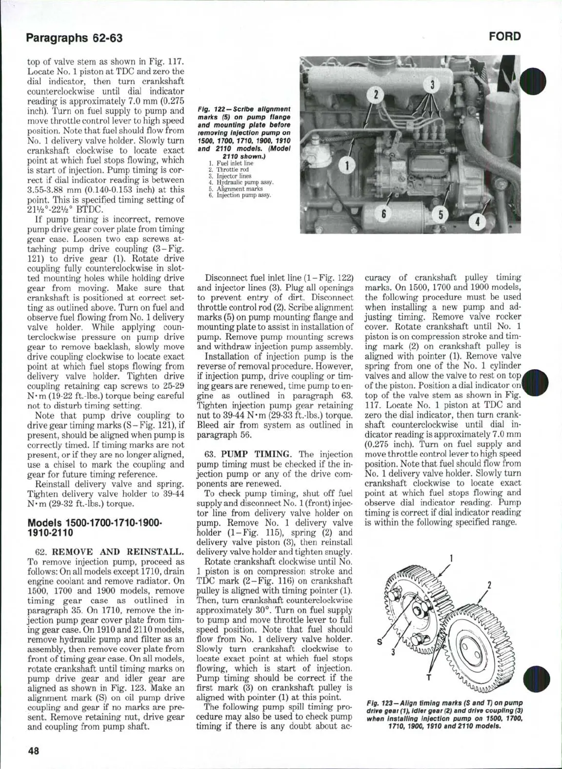
Fig, 122-Scribe alignment
marks (5) on pump flange
and mounting plate before
removing injection pump on
1500, 1700, 1710, 1900, 1910
and 2110 models. (Model
2110 shown.)
1.
Fuel inlet line
2.
Throttle rod
3.
Injector lines
4.
Hydraulic pump assy.
5.
Alignment marks
6. Injection pump assy.
Disconnect fuel inlet line (1-Fig. 122)
and injector lines (3). Plug all openings
to prevent entry of dirt. Disconnect
throttle control rod
(2).
Scribe alignment
marks (5) on pump mounting fiange and
mounting plate to assist in installation of
pump. Remove pump mounting screws
and withdraw injection pump assembly.
Installation of injection pump is the
reverse of removal procedure. However,
if injection pump, drive coupling or tim-
ing gears are renewed, time pump to en-
gine as outlined in paragraph 63.
Tighten injection pump gear retaining
nut to 39-44 N-m (29-33 ft.-lbs.) torque.
Bleed air from system as outlined in
paragraph 56.
63,
PUMP TIMING. The injection
pump timing must be checked if the in-
jection pump or any of the drive com-
ponents are renewed.
To check pump timing, shut off fuel
supply and disconnect
No,
1
(front) injec-
tor line from delivery valve holder on
pump. Remove No. 1 delivery valve
holder (1-Fig. 115), spring (2) and
delivery valve piston (3), then reinstall
delivery valve holder and tighten snugly.
Rotate crankshaft clockwise until No.
1 piston is on compression stroke and
TDC mark (2-Fig. 116) on crankshaft
pulley is aligned with timing pointer (1).
Then, turn crankshaft counterclockwise
approximately 30°, Turn on fuel supply
to pump and move throttle lever to full
speed position. Note that fuel should
fiow from No, 1 delivery valve holder.
Slowly turn crankshaft clockwise to
locate exact point at which fuel stops
fiowing, which is start of injection.
Pump timing should be correct if the
first mark (3) on crankshaft pulley is
aligned with pointer (1) at this point.
The following pump spill timing pro-
cedure may also be used to check pump
timing if there is any doubt about ac-
curacy of crankshaft pulley timing
marks. On 1500, 1700 and 1900 models,
the following procedure must be used
when installing a new pump and ad-
justing timing. Remove valve rocker
cover. Rotate crankshaft until No. 1
piston is on compression stroke and tim-
ing mark (2) on crankshaft pulley is
aligned with pointer (1). Remove valve
spring from one of the No. 1 cylinder
valves and allow the valve to rest on top
of the piston. Position a dial indicator on'
top of the valve stem as shown in Fig.
117.
Locate No. 1 piston at TDC and
zero the dial indicator, then turn crank-
shaft counterclockwise until dial in-
dicator reading is approximately 7.0 mm
(0,275 inch). Turn on fuel supply and
move throttle control lever to high speed
position. Note that fuel should fiow from
No,
1 delivery valve holder. Slowly turn
crankshaft clockwise to locate exact
point at which fuel stops fiowing and
observe dial indicator reading. Pump
timing is correct if dial indicator reading
is within the following specified range.
Fig. 123-Align timing marks (S and
T)
on pump
drive gear
(1),
idier gear
(2)
and drive
coupHng (3)
when Installing injection pump on 1500, 1700,
1710, 1900, 1910 and 2110 models.
48
 Loading...

