SHOP MANUAL
Paragraph 92
nator may be rated at either 20 amps or
35 amps.
If voltmeter reading increases but re-
mains below 15.5 volts (normal regu-
lated voltage is 13.8-14.8) and ammeter
reading is within 10 percent of rated
amps,
charging system is operating pro-
perly. If voltmeter reading exceeds 15.5
volts,
regulator is faulty. If voltmeter
reading remains the same or decreases
and ammeter reading is less than speci-
fied, perform the following maximum
field output test.
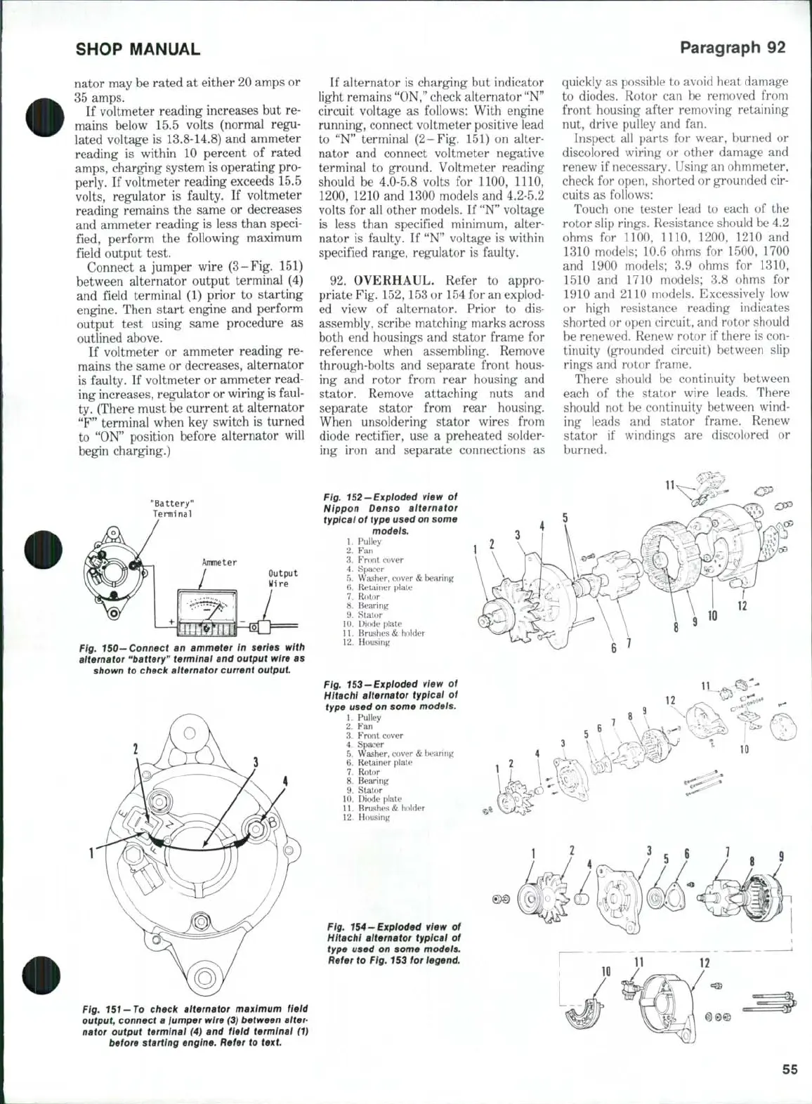
Connect a jumper wire (3-Fig. 151)
between alternator output terminal (4)
and field terminal (1) prior to starting
engine. Then start engine and perform
output test using same procedure as
outlined above.
If voltmeter or ammeter reading re-
mains the same or decreases, alternator
is faulty. If voltmeter or ammeter read-
ing increases, regulator or wiring is faul-
ty. (There must be current at alternator
"F"
terminal when key switch is turned
to "ON" position before alternator will
begin charging.)
"Battery"
Terminal
Ammeter
Output
Wire
Fig, 150-Connect an ammeter In series with
alternator
**battery"
terminal and output wire as
shown to check aiternator current output.
If alternator is charging but indicator
light remains "ON," check alternator "N"
circuit voltage as follows: With engine
running, connect voltmeter positive lead
to "N" terminal (2-Fig. 151) on alter-
nator and connect voltmeter negative
terminal to ground. Voltmeter reading
should be 4,0-5.8 volts for 1100, 1110,
1200,
1210 and 1300 models and 4,2-5.2
volts for all other models. If
"N"
voltage
is less than specified minimum, alter-
nator is faulty. If "N" voltage is within
specified range, regulator is faulty.
92.
OVERHAUL. Refer to appro-
priate Fig. 152,153 or 154 for an explod-
ed view of alternator. Prior to dis-
assembly, scribe matching marks across
both end housings and stator frame for
reference when assembling. Remove
through-bolts and separate front hous-
ing and rotor from rear housing and
stator. Remove attaching nuts and
separate stator from rear housing.
When unsoldering stator wires from
diode rectifier, use a preheated solder-
ing iron and separate connections as
Fig. 152-Expioded view of
Nippon Denso alternator
typical of type used on some
modeis,
1.
Pulley
2.
Fan
3.
Front cover
4.
Spacer
5.
Washer, cover
&
bearing
6. Retainer plate
7.
Rotor
8. Bearing
9. Stator
10.
DifMie plate
11.
Brushes & holder
12.
Housing
Fig. 153-Exploded view of
Hitachi alternator typical of
type used on some models.
1.
Pulley
2.
Fan
3.
Front cover
4.
Spacer
5.
Washer, cover
&
Itjearing
6. Retainer plate
7.
Rotor
8. Bearing
9. Stator
10.
Diode plate
11.
Brushes & holder
12.
Housing
quickly as possible to avoid heat damage
to diodes. Rotor can be removed from
front housing after removing retaining
nut, drive pulley and fan.
Inspect all parts for wear, burned or
discolored wiring or other damage and
renew if necessary. Using an ohmmeter,
check for open, shorted or grounded cir-
cuits as follows:
Touch one tester lead to each of the
rotor slip rings. Resistance should be 4.2
ohms for 1100, 1110, 1200, 1210 and
1310 models; 10,6 ohms for 1500, 1700
and 1900 models; 3,9 ohms for 1310,
1510 and 1710 models; 3.8 ohms for
1910 and 2110 models. Excessively low
or high resistance reading indicates
shorted or open circuit, and rotor should
be renewed. Renew rotor if there is con-
tinuity (grounded circuit) between slip
rings and rotor frame.
There should be continuity between
each of the stator wire leads. There
should not be continuity between wind-
ing leads and stator frame. Renew
stator if windings are discolored or
burned.
10
12
1
2
Fig. 154-Expioded view of
Hitachi aiternator typical of
type
used on some models.
Refer to Fig. 153 for legend.
Fig.
151
—To check alternator maximum field
output, connect a lumper wire (3) between
alter-
nator output terminal (4) and field terminal (1)
before starting engine. Refer to
text.
55
 Loading...

