Paragraphs 93-95
FORD
Check rectifier diodes by touching one
tester lead to diode terminal and touch
other lead to rectifier frame, then re-
verse test lead connections. The diodes
should show continuity in one direction
and high resistance in the other direc-
tion. If one or more diodes has high re-
sistance in both directions or low re-
sistance in both directions, renew rec-
tifier assembly.
Refer to the following specifications
for rotor and brush wear limits.
Models 1100-1110-1200-1210-1300
Rotor Slip Rings
Minimum Diameter 31.7 mm
(1.248 in.)
Maximum Runout 0.05 mm
(0.002 in.)
Brush Length -
Minimum 5.5 mm
(0.217 in.)
Models 1310-1510-1710
Rotor Slip Rings -
Minimum Diameter 30 mm
(1.181 in.)
Maximum Runout 0.05 mm
(0.002 in.)
Brush Length -
Minimum 8.5 mm
(0.335 in.)
Models 1500-1700-1900
Rotor Slip Rings -
Minimum Diameter 30.7 mm
(1.209 in.)
Maximum Runout 0.05 mm
(0.002 in.)
Brush Length -
Minimum 7 mm
(0.275 in.)
Models 1910-2110
Rotor Slip Rings -
Minimum Diameter 31.3 mm
(1.232 in.)
Maximum Runout 0,05 mm
(0,002 in.)
Brush Length -
Minimum 9 mm
(0.355 in.)
When reassembling alternator, solder
stator wire connections using resin core
solder. Hold rectifier terminals with
needlenose pliers to absorb heat during
soldering operation. Quickly cool sol-
dered connection with a damp cloth to
protect rectifier diodes. To hold brushes
in retracted position during assembly,
push brushes into holder and insert a pin
or wire through holes in rear housing
and brush holder.
SAFETY START SWITCH
Models 1100-1110-1200-1210-
1300-1500-1700-1900
93.
A safety start switch
(1
-
Fig.
155)
is located on left side of clutch housing
and is actuated by the clutch pedal. The
switch should prevent starter motor
from engaging unless clutch pedal is
fully depressed. Clutch linkage should be
adjusted correctly before adjusting safe-
ty start switch. Adjust position of switch
so that it passes current to energize
starter solenoid only when clutch pedal
is fully depressed.
Models 1310-1510-1710-1910-2110
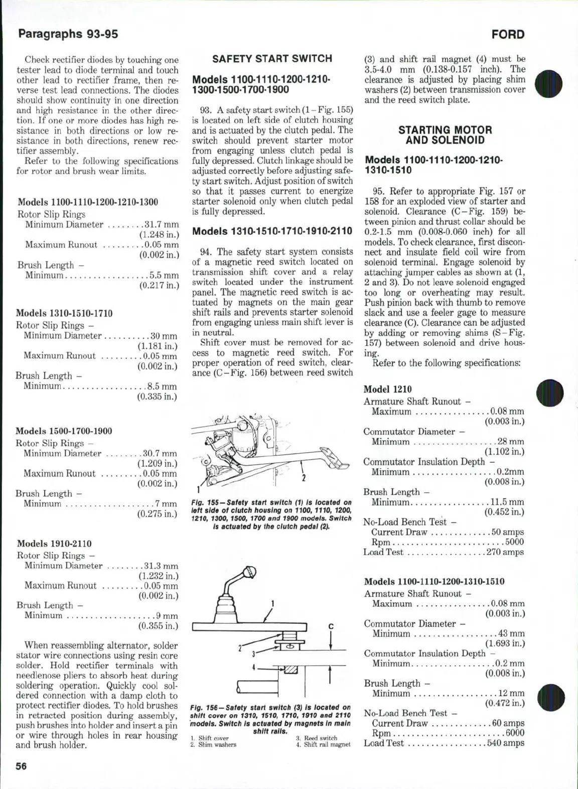
94.
The safety start system consists
of a magnetic reed switch located on
transmission shift cover and a relay
switch located under the instrument
panel. The magnetic reed switch is ac-
tuated by magnets on the main gear
shift rails and prevents starter solenoid
from engaging unless main shift lever is
in neutral.
Shift cover must be removed for ac-
cess to magnetic reed switch. For
proper operation of reed switch, clear-
ance (C-Fig. 156) between reed switch
Fig. i55-Safety start switch (1) Is located on
left side of clutch housing on 1100, 1110, 1200,
1210, 1300, 1500, 1700 and 1900 models. Switch
is actuated by the clutch pedal (2ji
1
2'
L
]
c
(
1
Fig. 156-Safety start switch (3) is located on
shift cover on 1310, 1510, 1710, 1910 and 2110
models. Switch is actuated by magnets In main
shift rails.
1.
Shift cover 3. Reed switch
2.
Shim washers 4. Shift rail magnet
(3) and shift rail magnet (4) must be
3.5-4.0 mm (0.138-0.157 inch). The
clearance is adjusted by placing shim
washers (2) between transmission cover
and the reed switch plate.
STARTING MOTOR
AND SOLENOID
Models 1100-1110-1200-1210-
1310-1510
95.
Refer to appropriate Fig. 157 or
158 for an exploded view of starter and
solenoid. Clearance (C-Fig. 159) be-
tween pinion and thrust collar should be
0.2-1.5 mm (0.008-0.060 inch) for all
models. To check clearance, first discon-
nect and insulate field coil wire from
solenoid terminal. Engage solenoid by
attaching jumper cables as shown at (1,
2 and 3). Do not leave solenoid engaged
too long or overheating may result.
Push pinion back with thumb to remove
slack and use a feeler gage to measure
clearance
(C).
Clearance can be adjusted
by adding or removing shims (S-Fig.
157) between solenoid and drive hous-
ing.
Refer to the following specifications:
Model 1210
Armature Shaft Runout -
Maximum 0.08 mm
(0.003 in,)
Commutator Diameter -
Minimum 28 mm
(1.102 in.)
Commutator Insulation Depth -
Minimum 0.2mm
(0.008 in.)
Brush Length -
Minimum 11.5 mm
(0.452 in,)
No-Load Bench Test -
Current Draw 50 amps
Rpm 5000
Load Test .270 amps
Models 1100-1110-1200-1310-1510
Armature Shaft Runout --
Maximum 0.08 mm
(0,003 in.)
Commutator Diameter -
Minimum 43 mm
(1.693 in.)
Commutator Insulation Depth -
Minimum 0.2 mm
(0.008 in.)
Brush Length -
Minimum
12
mm
(0.472 in.)
No-Load Bench Test -
Current Draw 60 amps
Rpm 6000
Load Test , 540 amps
56