Paragraphs 97-101
FORD
Models 1500-1700-1900-
1910-2110
97.
Refer to Fig. 162 for an exploded
view of starting motor and solenoid. Pin-
ion clearance (C-Fig. 159) should be
0.2-1.5 mm (0.008-0.060 inch) with
solenoid engaged. To check clearance,
disconnect and^ insulate field wire from
solenoid terminal. Engage solenoid by
attaching jumper cables (1, 2 and 3) to
locations indicated. Push pinion back to
remove slack and use a feeler gage to
measure clearance between pinion and
stop collar. Clearance can be adjusted by
adding or removing shims
(S
-
Fig.
162)
between solenoid and drive housing.
Refer to the following specifications:
Armature Shaft Runout -
Maximum 0.1 mm
(0.004 in.)
Commutator Diameter -
Minimum 40 mm
(1.575 in.)
Commutator Insulation Depth -
Minimum 0.2 mm
(0.008 in.)
Brush Length - Minimum
1500 and 1700 Models 11.5 mm
(0.452 in.)
All Other Models
15
mm
(0.590 in.)
No-Load Bench Test -
Current Draw 90 amps
Rpm 4000
Load Test
1500 and 1700 Models 900 amps
All Other Models 1300 amps
Model 1710
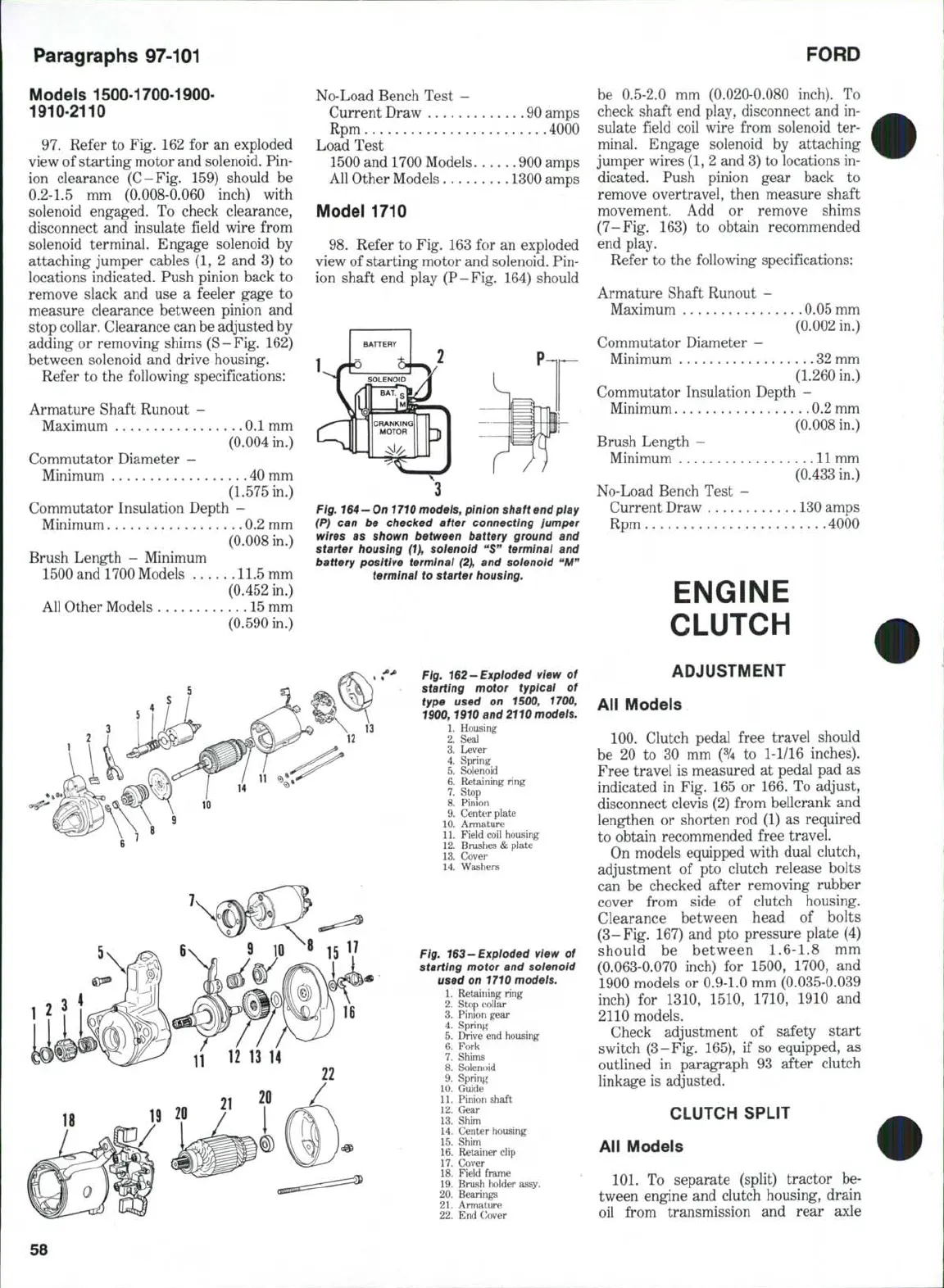
98.
Refer to Fig. 163 for an exploded
view of starting motor and solenoid. Pin-
ion shaft end play (P-Fig. 164) should
BATTERY
It
1
^SOLENOID
]
CRANKING
1
MOTOR
2
3
Fig.
164
—
Oni
710
models, pinion shaft end play
(P) can be checked after connecting lumper
wires as shown between battery ground and
starter housing (1}, solenoid **S" terminai and
battery positive terminai (2), and soienoid "M"
terminai to starter housing.
Fig. 162-Exploded view of
starting motor typicai of
type used on 1500, 1700,
1900,1910 and 2110 modeis.
1.
Housing
2.
Seal
3.
Lever
4.
Spring
5.
Solenoid
6. Retaining ring
7.
Stop
8. Pinion
9. Center plate
10.
Armature
11.
Field coil housing
12.
Brushes
&
plate
13.
Cover
14.
Washers
Fig. 163-Exploded view of
starting motor and solenoid
used on 1710 models.
1.
Retaining ring
2.
Stop collar
3.
Pinion gear
4.
Spring
5.
Drive end housing
6. Fork
7.
Shims
8. Solenoid
9. Spring
10.
Guide
11.
Pinion shaft
12.
Gear
13.
Shim
14.
Center housing
15.
Shim
16.
Retainer clip
17.
Cover
18.
Field frame
19.
Brush holder assy.
20.
Bearings
21.
Armature
22.
End C;over
be 0.5-2.0 mm (0.020-0.080 inch). To
check shaft end play, disconnect and in-
sulate field coil wire from solenoid ter-
minal. Engage solenoid by attaching
jumper wires
(1,
2 and 3) to locations in-
dicated. Push pinion gear back to
remove overtravel, then measure shaft
movement. Add or remove shims
(7-Fig. 163) to obtain recommended
end play.
Refer to the following specifications:
Armature Shaft Runout -
Maximum 0.05 mm
(0.002 in.)
Commutator Diameter -
Minimum 32 mm
(1.260 in.)
Commutator Insulation Depth -
Minimum 0.2 mm
(0.008 in.)
Brush Length -
Minimum
11
mm
(0.433 in,)
No-Load Bench Test -
Current Draw 130 amps
Rpm 4000
ENGINE
CLUTCH
ADJUSTMENT
All Models
100.
Clutch pedal free travel should
be 20 to 30 mm (% to
1-1/16
inches).
Free travel is measured at pedal pad as
indicated in Fig, 165 or 166. To adjust,
disconnect clevis (2) from bellcrank and
lengthen or shorten rod (1) as required
to obtain recommended free travel.
On models equipped with dual clutch,
adjustment of pto clutch release bolts
can be checked after removing rubber
cover from side of clutch housing.
Clearance between head of bolts
(3-Fig. 167) and pto pressure plate (4)
should be between
1.6-1.8
mm
(0.063-0.070 inch) for 1500, 1700, and
1900 models or 0.9-1.0 mm (0,035-0.039
inch) for 1310, 1510, 1710, 1910 and
2110 models.
Check adjustment of safety start
switch (3-Fig. 165), if so equipped, as
outlined in paragraph 93 after clutch
linkage is adjusted.
CLUTCH SPLIT
All Models
101,
To separate (split) tractor be-
tween engine and clutch housing, drain
oil from transmission and rear axle
58
 Loading...

