CONTROLS, INSTRUMENTS AND.OPERATION-·
--
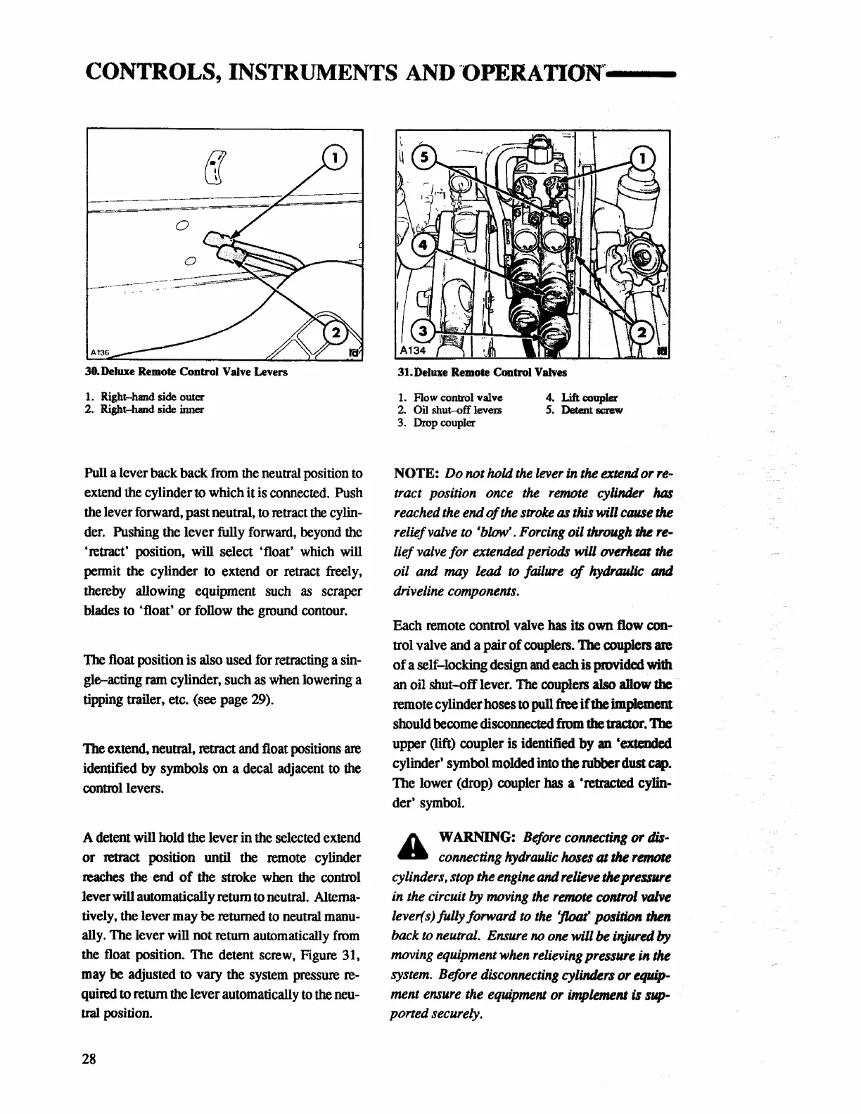
30.
Deluxe
Remote Control
Valve
Levers
1. Right-hand side outer
2. Right-hand side inner
Pull a lever back back
from
the
neutral position
to
extend
the
cylinder to which it
is
connected.
Push
the
lever forward. past neutral, to retract
the
cylin-
der.
Pushing the lever fully
forward,
beyond
the
'retract' position,
will
select 'float'
which
will
permit
the
cylinder
to
extend or retract
freely,
thereby
allowing equipment such
as
scraper
blades
to 'float' or follow
the
ground
contour.
The float position is also used for retracting a
sin-
gle-acting
ram
cylinder,
such
as
when
lowering
a
tipping trailer, etc.
(see
page
29).
The extend, neutral, retract
and
float positions
are
identified
by
symbols on a decal adjacent to
the
control levers.
A detent
will
hold the lever in the selected extend
or retract position
until
the
remote
cylinder
reaches the end
of
the stroke
when
the
control
lever will automatically return to neutral.
Alterna-
tively, the lever may be returned
to
neutral
manu-
ally. The lever will not return automatically
from
the
float position. The detent screw,
Figure
31,
may
be
adjusted to vary
the
system
pressure
re-
quired
to
return
the
lever
automatically
to
the
neu-
tral position.
28
31.Deluxe Remote Control
Valves
1.
Flow control valve
4.
Lift
coupler
2.
Oil
shut-off levers
5.
Detent
screw
3.
Drop coupler
NOTE:
Do
not hold
the
lever
in
the
extend or
re-
tract position
once
the
remote
cylinder
has
reached
the
end
of
the
stroke
as
this will
cause
the
relief
valve
to
'blow'.
Forcing
oil
through
the
re-
lief
valve
for extended periods will overheat
the
oil
and
may
lead
to
failure
of
hydraulic
and
driveline
components.
Each remote control
valve
has
its
own
flow
con-
trol valve
and
a pair
of
couplers.
The
couplers are
of a self-locking design
and
each
is provided with
an
oil
shut-off lever.
The
couplers
also
allow
the
remote cylinder hoses to pull free
if
the
implement
should become
discollllected
from
the tractor.
1be
upper (lift) coupler
is
identified
by
an 'extended
cylinder' symbol molded into the rubber dust
cap.
The
lower (drop) coupler has a 'retracted
cylin-
der' symbol.
A
WARNING:
Before
connecting
or
dis·
4lla
connecting
hydraulic
hoses at
the
remote
cylinders,
stop
the
engine
and
relieve the
pressUTe
in
the
circuit
by
moving
the
remote
control
valve
lever(s)fully forward
to
the
'float
position
then
back
to
neutral.
Ensure
no
one
will
be
injured
by
moving equipment
when
relieving
pressure in
the
system.
Before
disconnecting
cylinders or equip-
ment
ensure
the
equipment
or implement is
sup-
ported securely.