EasyManuals Logo

Foxconn H67M-V User Manual

Foxconn H67M-V
109 pages
To Next Page IconTo Next Page
To Previous Page IconTo Previous Page
Page #11 background imageLoading...
Page #11 background image
1
4
1-2 Layout
Note : The above motherboard layout is for reference only, please refer to the physical
motherboard for detail.
1. 4-pin ATX 12V Power Connector
2. SYS_FAN1 Header
3. PCI Express x16 Slot
4. PCI Express x1 Slot
5. PCI Express Slot
6. CD_IN Connector
7. Front Audio Connector
8. SPDIF_OUT Connector
9. Speaker Connector
10. Front USB Connectors
11. Clear CMOS Jumper
12. TPM Connector
13. SATA Connectors
14 Front Panel Connector
15. Chipset: Intel
®
H67
16. 24-pin ATX Power Connector
17. LPT Connector
18. INTR2 Connector
19. COM1 Connector
20. DDR3 DIMM Slots
21. CPU_FAN Header
22. LGA1155 CPU Socket
1
7
2
16
6 5
8
10
12
13
17
19
21
22
14
20
11
18
9
15
34

Table of Contents

Questions and Answers:

Question and Answer IconNeed help?

Do you have a question about the Foxconn H67M-V and is the answer not in the manual?
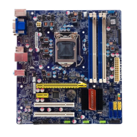
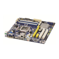
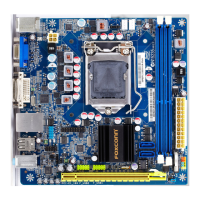
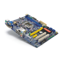
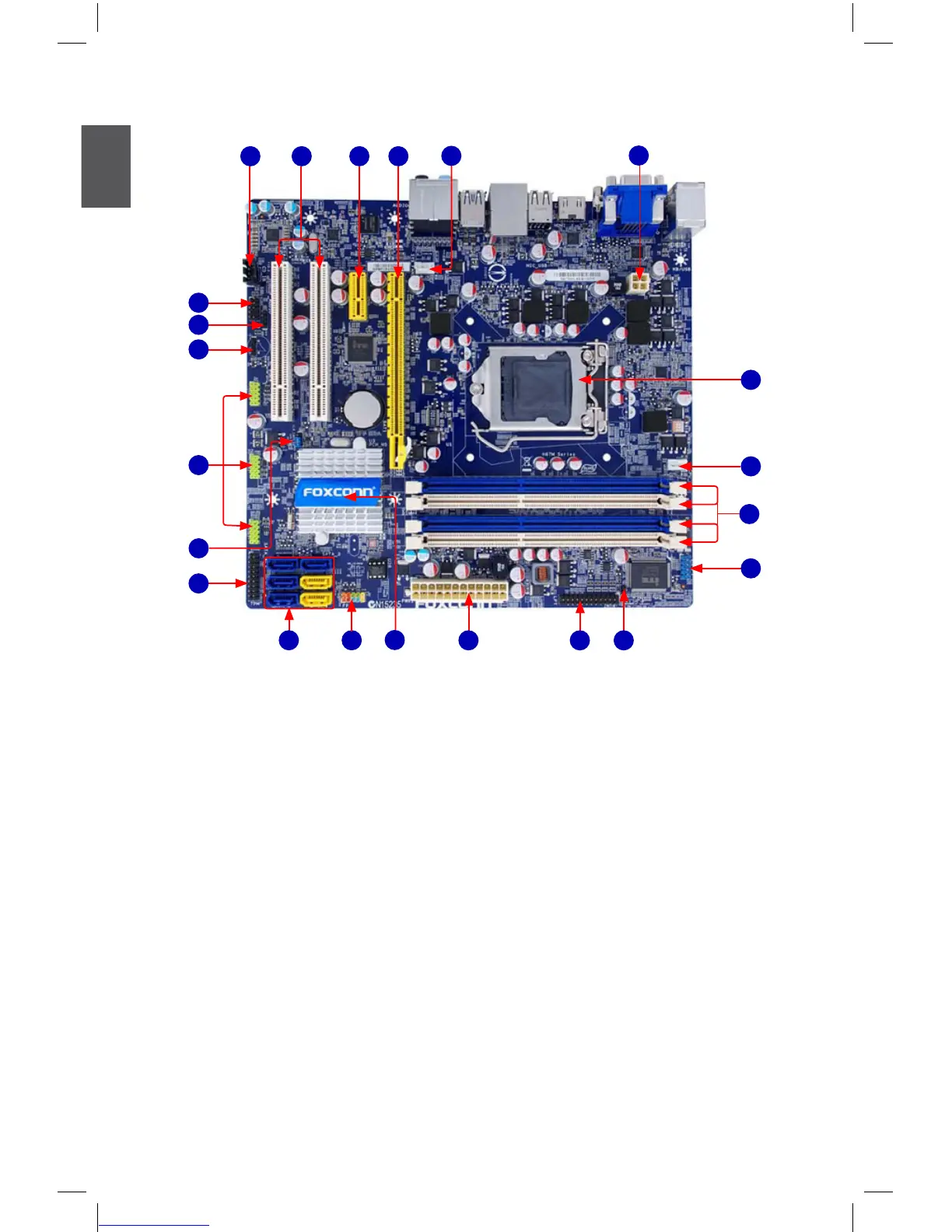
Foxconn H67M-V Specifications

General IconGeneral
Form FactorMicro ATX
ChipsetIntel H67
SocketLGA 1155
Maximum Memory32GB
Memory StandardDDR3 1333/1066 MHz
PCI Express x161
SATA Ports4 x SATA 3Gb/s, 2 x SATA 6Gb/s
AudioRealtek ALC887 8-Channel HD Audio
Memory Slots4
Expansion Slots1 x PCI
USB Ports10 (4 on back panel, 6 via headers)
Video OutputsDVI-D
LANRealtek RTL8111E Gigabit LAN

Related product manuals