17
6.3 Grid Connection
Step 1: Grid String Connection
H3/AC3 series inverters are designed for three-phase grid. Per voltage range is 220/230/240V;
frequency is 50/60Hz. Other technical requests should comply with the requirement of the local public
grid.
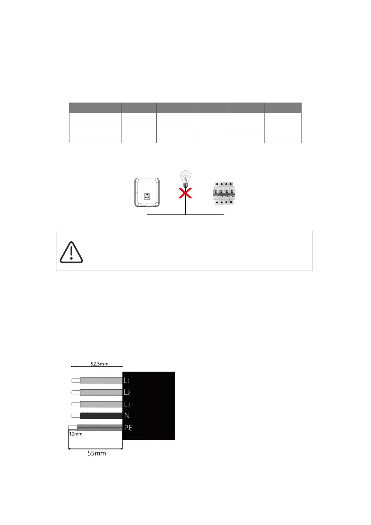
WARNING!
A micro-breaker for max output overcurrent protection device shall be installed between
inverter and grid, and the current of the protection device is referred to the table above,
any load SHOULD NOT be connected with the inverter directly.
Step 2: Grid Wiring
• Check the grid voltage and compare with the permitted voltage range (refer to technical data).
• Disconnect the circuit-breaker from all the phases and secure against re-connection.
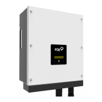
• Trim the wires:
- Trim all the wires to 52.5mm and the PE wire to 55mm.
- Use the crimping pliers to trim 12mm of insulation from all wire ends as below.
Note: Please refer to local cable type and color for actual installation.
Model (kW) 5.0 6.0 8.0 10.0 12.0
Cable (ON-GRID) 4.0-6.0mm² 4.0-6.0mm² 4.0-6.0mm² 4.0-6.0mm² 4.0-6.0mm²
Cable (EPS) 4.0-6.0mm² 4.0-6.0mm² 4.0-6.0mm² 4.0-6.0mm² 4.0-6.0mm²
Micro-Breaker 63A 63A 63A 63A 63A
L1/L2/L3: Brown/Red/Green or Yellow Wire
N: Blue/Black Wire
PE: Yellow & Green Wire