Do you have a question about the FPT CURSOR 13 and is the answer not in the manual?
Explains warning symbols used in the manual for safety and damage prevention.
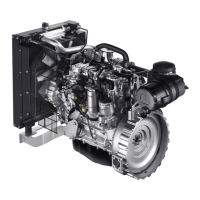
Details engine identification through serial number, construction date, engine type, and barcode.
Provides detailed technical data including cycle, supply, bore, stroke, power, torque, and speeds.
Details the Common Rail fuel system, including the high-pressure pump and electro-injectors.
Explains the engine lubrication system, driven by a gear pump, and the role of the heat exchanger.
Describes the closed-circuit cooling system, its components like water pump, thermostat, and heat exchanger.
Details the turbocharging system components: air filter, turbocharger, and intercooler.
Illustrates and labels the main electrical components of the engine, including sensors, ECU, and starter motor.
Provides schematic diagrams for engine side wiring, showing connections for sensors, injectors, and ECU.
Details the pinout for the 96-pin ECU connector, listing signals for various engine sensors and actuators.
Details CRIN 3.3 injectors and the Rail Pressure Sensor (RSD 4), including electrical connections and specifications.
Explains the inductive crankshaft sensor, its location, function for piston position and engine speed, and specifications.
Provides specifications for the alternator, including supplier, voltage, current, speed, and belt tension.
Covers main operations for cylinder head overhaul, including hydraulic tightness checks and valve removal.
Outlines measurements for main journals and crankpins, including tolerances and selection classes.
Provides engine type, cycle, supply, injection, bore, stroke, power, torque, and distribution data.
Provides detailed torque specifications for various screws, nuts, and fittings used in engine assembly.
Provides essential safety regulations for maintenance personnel, covering general precautions and accident prevention.
Details necessary precautions for a safe work environment, including room ventilation, first-aid, and fire safety.
Outlines specific accident prevention measures, such as protective clothing, handling pressurized fluids, and avoiding hazards.
Lists critical precautions during maintenance, including handling hot systems, flammable materials, and electrical circuits.