Do you have a question about the FPT CURSOR 87TE4 and is the answer not in the manual?
Important safety information regarding engine alterations and their consequences.
Actions to perform before starting the engine each time.
Procedures for starting and stopping the engine.
Information about the optional engine pre-heating device.
List and function of fuses in the interconnection electrical unit.
List and function of relays in the interconnection electrical unit.
Configures engine speed for 50/60 Hz power generation using JP1 switch.
Sets operating mode (Diagnosis or Operating) via JP2 switch.
Controls the pre-heating warning light status via JP3 switch.
Activates or deactivates the fuel pre-heating system via JP4 switch.
Indicates availability or unavailability of the CAN line connection via JP5 switch.
Button to request diagnostic blink codes for troubleshooting.
Indicator for displaying diagnostic blink codes.
Checks and procedures related to engine cooling liquid.
Steps for refilling the cooling liquid.
Checks related to engine oil pressure and level.
Roles and responsibilities for maintenance tasks.
Safety precautions to prevent accidents during maintenance.
Procedure for adjusting valve clearance in rocker arms.
Steps to check and change engine oil.
Steps to prepare the engine for extended storage.
How to handle accelerator circuit failures.
Procedures for handling engine malfunctions in emergency situations.
Procedures for extinguishing engine fires during emergencies.
First aid procedures for burns and scalds during emergencies.
This document serves as a comprehensive use and maintenance guide for the FPT Cursor 87TE4 G-Drive Engines. It outlines essential procedures for operation, routine checks, and addressing potential malfunctions, ensuring safe and efficient use of the engine.
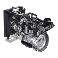
The FPT Cursor 87TE4 is a G-Drive engine designed for power generation. It is a 4-stroke diesel engine with 6 cylinders in line, featuring a bore x stroke of 117 x 135 mm and a total displacement of 8,700 cm³. The engine incorporates a turbo aftercooler and is electronically managed with a Common Rail injection system. Its direction of rotation is anticlockwise when viewed from the flywheel side. The electrical system operates at 24 V, requiring accumulators with a capacity of 180 Ah or above and a discharge current of 1200 A or above.
The engine's electronic control unit (ECU) is central to its operation, managing various functions and ensuring optimal performance. An interconnection electrical unit is fitted to the engine to facilitate correct electrical functioning, with fuses and relays controlling engine start, diagnosis, fuel heating, and ECU power supply. The ECU is programmed to adopt safety strategies in response to conditions that might put the engine at risk, such as low voltage in the electrical system or accelerator circuit malfunctions.
Before starting the engine, several preliminary checks are crucial. Users must verify the levels of technical fluids (fuel, engine oil, and coolant) and top them up if necessary. The air aspiration filter should be checked for blockages, indicated by a "red" sign on the mechanical indicator or an alarm on the instrument panel if an electrical blockage sensor is present. It is imperative to ensure no combustible vapors or gases are present in the operating area and that closed areas are adequately ventilated.
The engine offers programmable functions through JP switches, allowing selection of engine speed (1,800 rev./min for 60 Hz power generation or 1,500 rev./min for 50 Hz power generation), mode (diagnosis or operating), pre-heating warning light connection, and fuel pre-heating relay status.
For proper use, it is important to ensure sufficient fuel in the tank and avoid prolonged idling, which can negatively impact performance. Actual power values should always comply with the rated values in the technical documentation. During operation, the cooling liquid temperature and oil pressure must be regularly monitored to ensure they remain within normal values. Emergency power unit engines require frequent overhauls to ensure prompt starting when needed.
In case of an accelerator electronic circuit malfunction, the engine adopts an "accelerated minimum speed running" strategy. This allows continued operation in emergency mode, either with the running speed stabilized at 750 rpm (if the accelerator lever does not respond) or with partial response where speed gradually increases up to 2000 rpm and rapidly decreases to 750 rpm when the lever is returned to minimum. If the recharging system malfunctions, the ECU increases the minimum running speed, prompting a check of the battery and system components.
Maintenance operations are categorized into controls, periodic maintenance, and special maintenance, with specific personnel qualifications required for each. Controls can be performed by workshop technicians or the machine user, periodic maintenance by qualified personnel with suitable equipment, and special maintenance by qualified personnel from Authorized Service Centres.
Routine checks include daily inspection of oil and coolant levels, cleanliness of heat exchangers, and exhaust pipes. Monthly, the air filter should be checked. Half-yearly checks involve tightening and cleaning battery clamps, topping up electrolyte levels, and checking the blow-by filter.
Scheduled maintenance intervals vary:
When performing maintenance, safety precautions are paramount. Always wear heavy-duty footwear, overalls, protective gloves, and goggles. Avoid loose clothing, rings, bracelets, and necklaces near moving parts. Use high-pressure air jets with goggles and ensure proper ventilation when working with batteries due to the presence of sulfuric acid.
Specific procedures are detailed for various maintenance tasks:
For long periods of inactivity (over two months), specific preparation steps are required to prevent oxidation. This involves draining lubricants, filling with protective oil, draining fuel, connecting to a tank of protective fluid, nebulizing protective oil into the turbocharger inlet, and sealing all openings. These steps should be repeated every six months. Restarting the engine after inactivity involves draining protective oil, refilling with lubricant, draining protective fluid from the fuel circuit, removing seals, connecting fuel circuits, filling with coolant, and running the engine until idling speed stabilizes.
Disposal of waste materials such as starter batteries, used lubricants, water/antifreeze mixtures, filters, and cleaning materials must be done through specialized Collection Centres, adhering to local regulations.
| Displacement | 8.7 L |
|---|---|
| Number of Cylinders | 6 |
| Aspiration | Turbocharged |
| Fuel System | Common Rail |
| Bore x Stroke | 117 x 135 mm |
| Engine Type | Diesel |
| Cooling System | Liquid Cooled |
| Engine Model | FPT CURSOR 87TE4 |