AutoTune for Motorola APX Series Radios User Guide
4.16. Symbol Deviation
NOTE: This test requires an analyzer with P25 Conventional test mode (R8-P25
option) capability.
The purpose of this procedure is to measure the radio transmitter’s P25 Phase 1
Symbol Deviation at a given frequency. Symbol Deviation provides the deviation
measurement at symbol decision times. The TIA/EIA-102.CAAB measurement standard
max limit is 1800 Hz +/-180 Hz. This is a test only; there is no alignment.
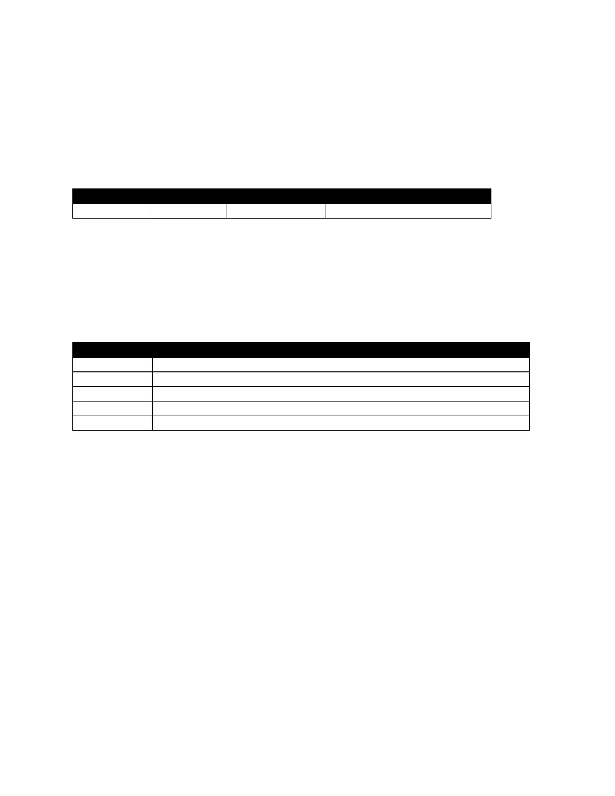
Table 4-32. Analyzer Configuration for Symbol Deviation test
4.16.1. Test
The analyzer is setup as specified in this section’s Analyzer Configuration table. The
radio is placed into Test Mode at the lowest Tx Test Frequency and configured to
generate the indicated P25 waveform signal. The analyzer measures the Symbol
Deviation response which is compared against test limits and the final results are written
to the log file.
Pass or Fail. Measured Symbol Deviation is within Max Limit
Measured Symbol Deviation at Frequency
Minimum Limit (inclusive) for Symbol Deviation to Pass
Maximum Limit (inclusive) for Symbol Deviation to Pass
Table 4-33. Symbol Deviation test results
 Loading...