3-Axis Gyro use introduction
EN
11
Item No.:FJ310
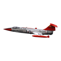
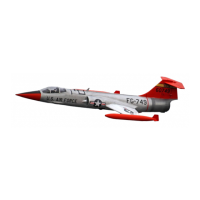
F-104S Starfighter
The F104 control board has two functions:
Control the function of the LED lights and gear doors
Reduce cable clutter in battery compartment.
1. .
2.
A
B
C
A-Screws
B-
C-
(PA3x8mm 4pcs)
Control board
Control board mount
Gyro
Screws
(PA2.3x8 4pcs)
Fix board
Fix board
AIL servo
1.
2.
3.
4.
5.
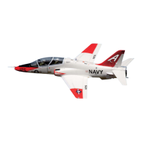
Ensure the gyro is installed correctly.
Connect the servo cables of the elevator, rudder and ailerons to the Gyro output port.
Use 3 connection wires to connect the gyro input port to the corresponding channels of the receiver.
If your receiver has enough channels, you can use another connection wire to connect gyro and receiver and assign
an off/on gyro switch.。
For the Gyro use introduction,
please refer to the Gyro user manual.
ELE servo
RUD servo
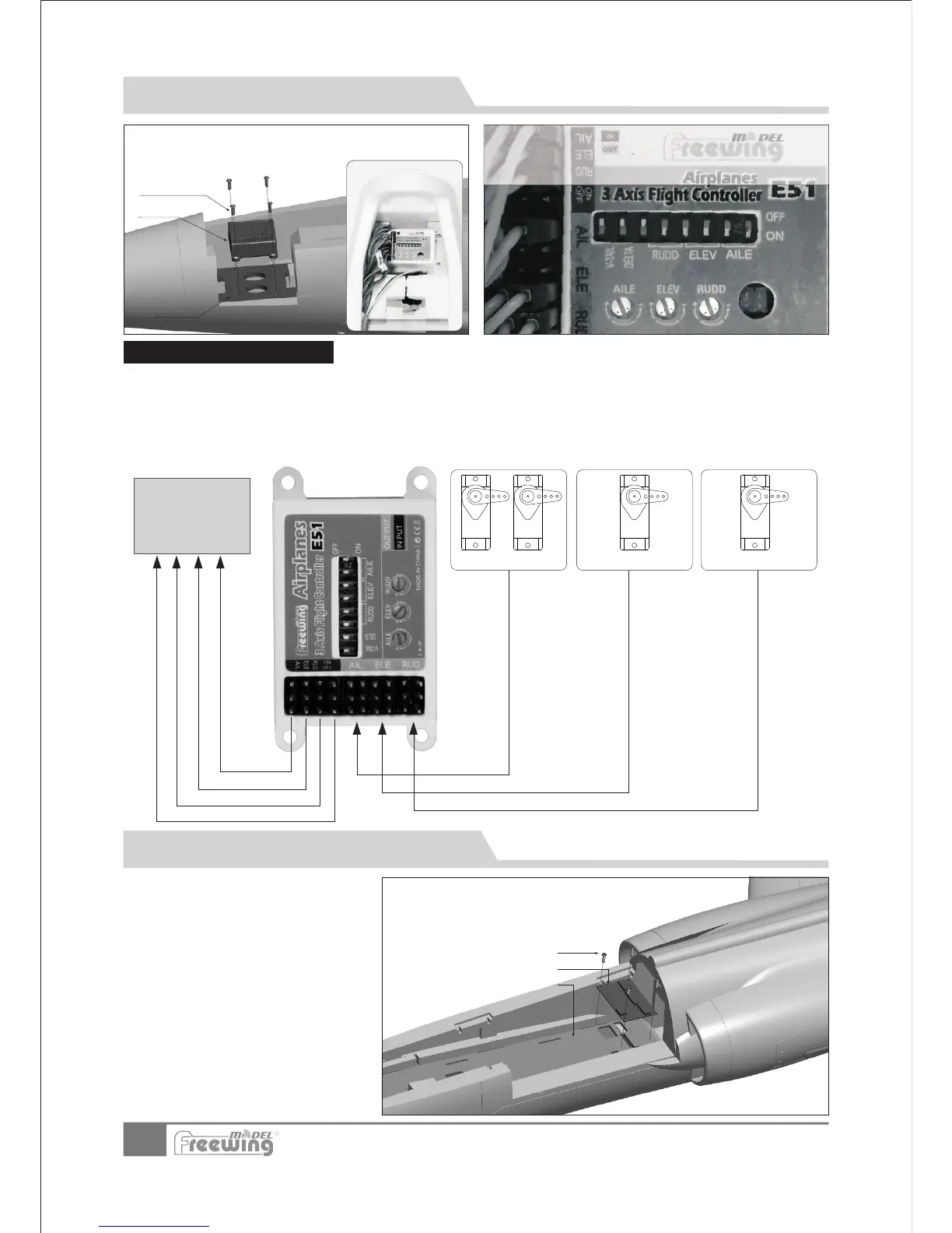
Use 4 screws to secure the gyro to the board at the front of battery
compartment. Make sure the gyro decal is facing toward the nose
cone when installed.
Gyro connection diagram
Receiver
Control Board Introduction and Use
R
This gyro was set up at the factory to default sensitivity.
You can make small adjustments according to flight
c
onditions. If you need to restore the gyro to the factory
default settings, refer to this photo for directions.
Refer to the channel assignments on the
Control Board. Connect the servo cables to
the Control Board with the exception of the
aileron, elevator and rudder which are
connected to the output of the gyro. After
all the connections are made and tested,
use the 4 screws to attach the control board
to the fuselage .