EN
14
Item No.:FJ310
F-104S Starfighter
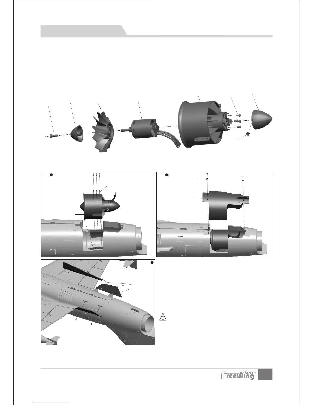
1.Place the“motor(D)”into the“ducted fan housing(C) ”.
2.Attach the motor with 4“cup head screws(B)”.
3.Put the“rotor(E)”in the motor shaft.
(During this process,please note the hardware platform of rotor should be aligned with the motor shaft platform)
4.Use“spinner(F)”to cover the rotor,and lock it in place with “cup-head-screw(G)”.
5.Attach the“tail fan cowl(A)”to the bottom of “ducted fan housing(C)” and lock it in place with 2 “Grub screws(H)”.
A
B
C
D
E
F
G
H
HM 4x14
M3x3
Hm3x8
N
1
Step
2
Step
3
Step
Power System Installation
Accessories name and specification
Note:When ESC and battery connected, do
not touch them by hand to avoid accidental injury.
When testing EDF, please use a safety test stand and
again, do not touch the unit!
EDF power system
Screws
Screws
Fan cover
Screws
(
(PA3x8mm 4pcs)
(PA3x8mm 4pcs)
PWA3x12mm 6pcs)
Fuselage
Fin
I -
J -
K -
L -
M-
N -
O-
R