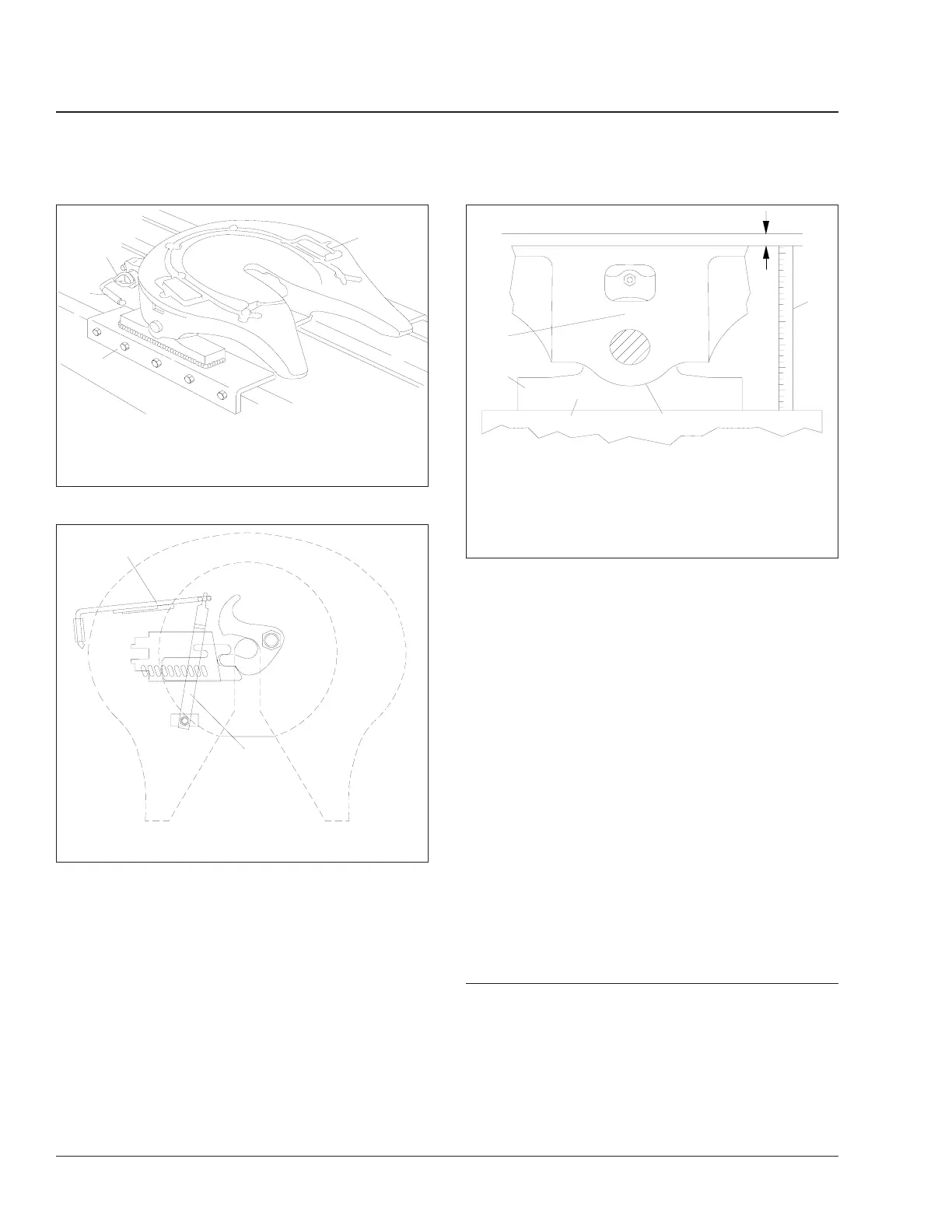
frame rail to the top of the fifth wheel plate (Ref.
1). Pry up on the fifth wheel plate (Ref. 4) below
the pin boss, and measure the vertical move-
ment (Ref. 5). The bracket connection provides a
9/32-inch (7-mm) vertical clearance to provide
cushioning and to avoid downward pin-loading
while retaining minimum plate lift. If the plate lift
(Ref. A) exceeds 5/16 inch (8 mm) as a result of
wear or rubber deterioration, install new, stan-
dard or oversized bracket-shoe rubber pads; see
Group 31 of the
Century Class Trucks Workshop
Manual
for replacement instructions.
NOTE: Do not measure plate lift immediately
after a trailer has been uncoupled from the fifth
wheel. The rubber may have taken a temporary
set, which will normally recover after being un-
coupled for a short period of time.
8. Check all mounting bolts for signs of fatigue, and
tighten them to the proper torque. For torque
specifications, see Group 00. Inspect all angles,
plates, and brackets for cracks or other damage.
9. Replace cracked, worn, or damaged parts with
new parts. Replace all loose mounting bolts with
5/8–11 SAE grade 8 bolts, grade C locknuts, and
hardened washers.
Do not
re-use bolts, nuts,
and washers on fifth wheel mountings.
10. After inspecting the fifth wheel, lubricate all mov-
ing parts with a chassis or multipurpose grease.
See Maintenance Operation 31–02 for lubrica-
tion instructions.
31–02 Fifth Wheel Lubrication
To maintain proper fifth wheel operation, always lubri-
cate the fifth wheel after an inspection has been
performed.
IMPORTANT: Lubricate the fifth wheel:
• After power washing, or steam cleaning.
f310353b
1
2
3
4
11/28/95
1. Lubricant Grooves
2. Safety Latch
3. Lock Control Handle
4. Mount
Fig. 3, Simplex Series Fifth Wheel
09/15/95
f310470
1
2
1. Operating Handle 2. Lever Bar
Fig. 4, Lever Bar and Operating Handle Alignment
f310475
08/31/95
1
2
3
A
4
5
A. Extended Top Plate Lift Height
1. Fifth Wheel Top Plate
2. Fifth Wheel Frame Mount
3. Frame Rail
4. Lifting Point
5. Static Top Plate Height
Fig. 5, Measuring Fifth Wheel Top Plate Lift
Frame and Frame Components31
Century Class Trucks Maintenance Manual, January 200731/4