5. The lever bar and operating handle must be in
proper alignment. See Fig. 4. Compare the lever
bar and operating handle alignment to a new, or
a properly operating lever bar and operating
handle. Replace any bent or misaligned lever bar
or operating rod.
6. Check all cotter pins for cracking or damage. Re-
place any cotter pin that shows any signs of
damage.
7. Level the fifth wheel plate to a horizontal posi-
tion. Measure the height from a stationary
mounting point (see Fig. 5, Ref. 3), such as the
08/29/95
f310472
12
11
13
1
2
3
4
5
6
10
8
9
18
17
15
7
16
15
14
14
13
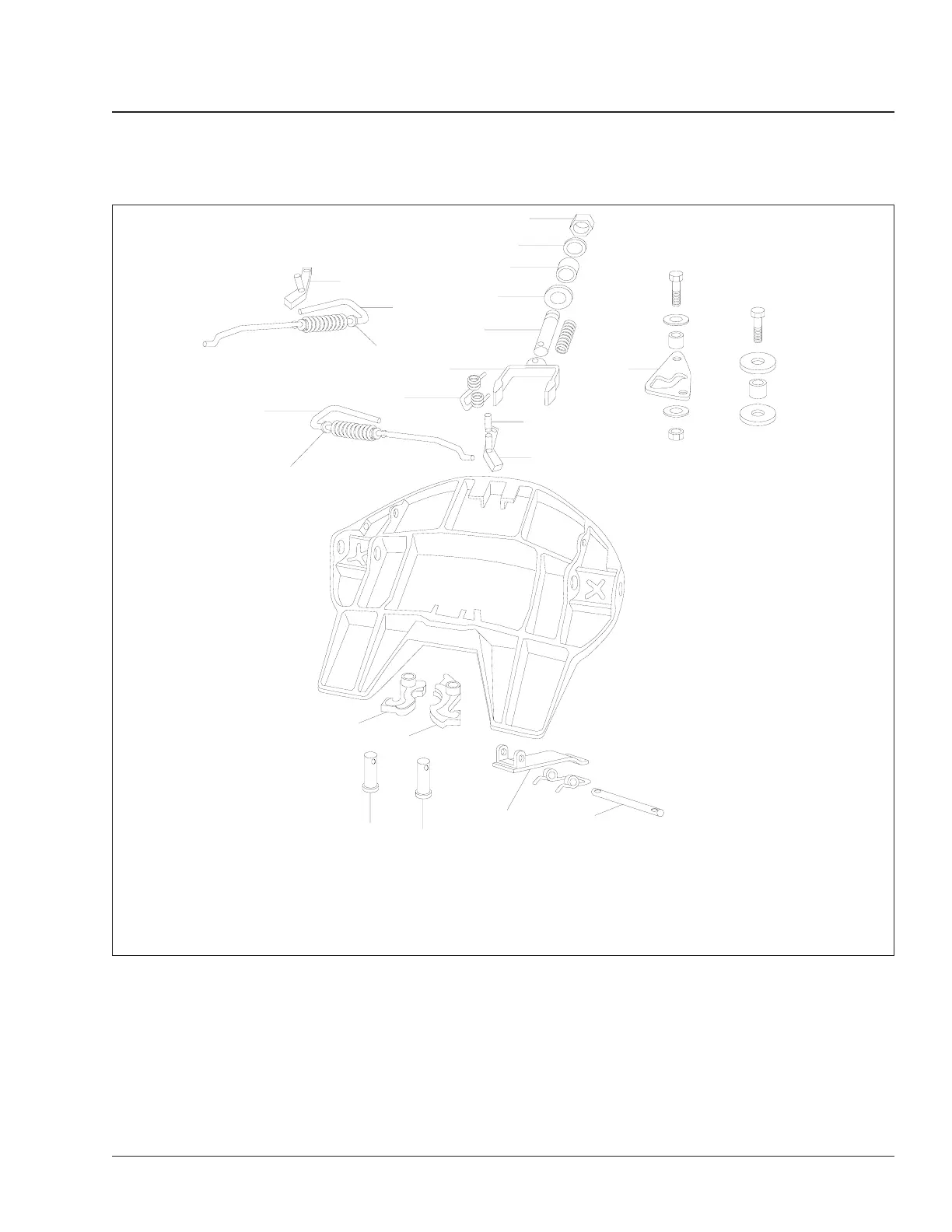
1. Locknut, 3/4–16
2. Washer
3. Rubber Washer
4. Lock Adjustment Tag
5. Yoke Shaft
6. Yoke Sub-Assembly
7. Torsion Spring
8. Roll Pin
9. Secondary Lock, Right-Hand
10. Cam Plate
11. Lock Guard
12. Pin
13. Lock Pin
14. Lock Jaw
15. Washer
16. Right-Hand Release Handle
17. Left-Hand Release Handle
18. Secondary Lock, Left-Hand
Fig. 2, Holland Fifth Wheel
Frame and Frame Components 31
Century Class Trucks Maintenance Manual, January 2007 31/3