(123 N·m). Replace the midship bearing assem-
bly if the rubber cushion is worn or oil-soaked.
5. Check the slip-joints for spline wear by trying to
bend the sleeve-yoke and splined shaft back and
forth (Fig. 2). If looseness is greater than 0.007
inch (0.18 mm), replace both the sleeve-yoke
and the splined shaft.
6. Check the driveshaft tubes for dents, bends,
twists, or other damage. If any tube appears to
be damaged, remove the driveshaft and check
the runout on the tube. If the tube is not straight
(and cannot be straightened) within 0.015 inch
(0.38 mm) on the slip-joint seal surface of the
splined shaft, 0.020 inch (0.51 mm) on the tube
3 inches (76 mm) from the front and rear welds,
and 0.025 inch (0.635 mm) at the center of the
tube, replace the tube. See Fig. 3.
If the driveshaft tube requires straightening or
replacement, balance the repaired driveshaft be-
fore installing it. See Group 41 of the
Business
Class
®
Trucks Service Manual
.
7. Check the driveshaft for missing balance
weights, and for debris build-up. Remove any
build-up. If any balance weights are missing, re-
f410057a
10/06/94
1
2
3
5
6
4
2
4
7
16
15
14
13
18
17
9
8
3
7
10
11
12
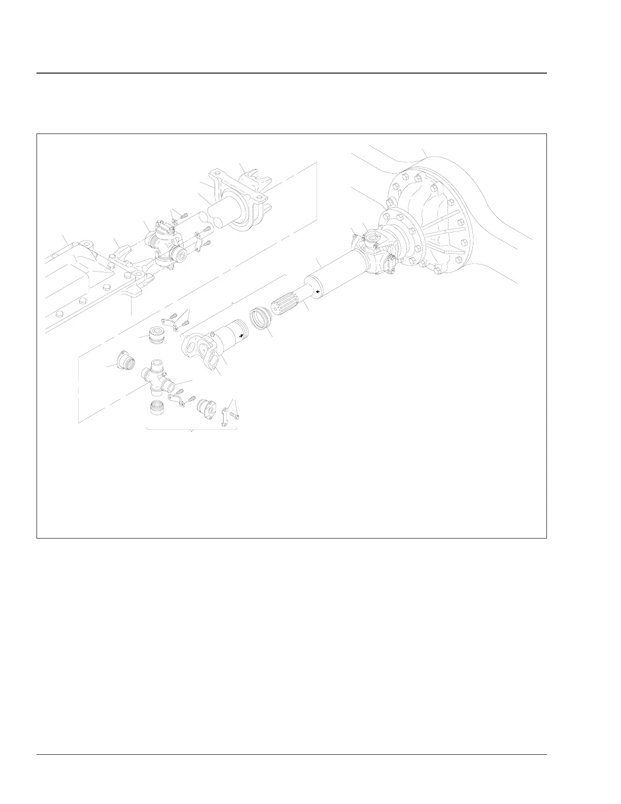
NOTE: Not all fasteners are shown.
1. Transmission
2. Half-Round End Yoke
3. U-Joint Assembly
4. Yoke Strap and Capscrew
5. Coupling Shaft
6. Midship Bearing and Mount
7. Bearing Cup
8. Slip-Joint Assembly
9. Driveshaft Tube
10. Driveshaft Yoke
11. Input Shaft Half-Round End
Yoke
12. Rear Axle
13. Splined Shaft
14. Dust Seal
15. Sleeve Yoke
16. Full-Round-Yoke Lug
17. U-Joint Cross
18. Lockplate and Capscrew
Fig. 1, Driveline Assembly With Midship Bearing For Single-Axle Installation
Driveline41
Business Class Trucks Maintenance Manual, January 199841/2