32
Genuine OEM Parts 1.800.233.4823 www.morganolsonparts.com
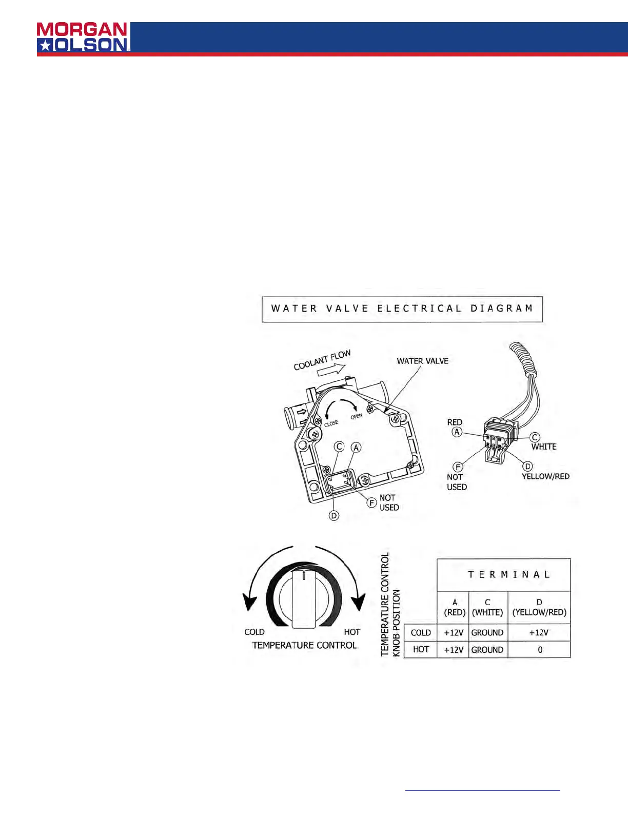
Figure 5
POSSIBLE CAUSE #3 - Control Panel Selector Switch is defective
CORRECTIVE ACTION - With the ignition turned to Accessory, unplug each of the connectors
from the Plenum servo motors and test according to the information in the Electrical Connection
To Plenum Servo Motors Diagram ( Figure 5).
If the test fails to nd agreement with the Diagram, there is a good possibility that the Mode Selec-
tion Switch at the control panel is defective.
Replace the Mode Selection Switch.
SECTION B: TEMPERATURE CONTROL PROBLEMS
PROBLEM B-1, Air temperature cannot be controlled
POSSIBLE CAUSE #1 - Water valve not operating
CORRECTIVE ACTION -
Valve may not be receiving a
signal from the control panel,
or valve is defective. Discon-
nect the electrical connector
from the valve. With the igni-
tion switch turned to Acces-
sory, check for the presence
of 12 volts between the red
wire (+12V) and the white wire
(ground) as noted in the
Wa-
ter Valve Electrical Diagram.
(Figure 5).
The yellow/red
signal wire will provide +12V
(full cold position) dropping to
zero volts (full hot position) as
the temperature control knob
is rotated clockwise. If the
condition at the connector is in
agreement with the Diagram,
proceed as follows:
Step 1 Disconnect the water
valve from the 5/8" heater hoses.
Step 2 Carefully inspect the four
small terminal pins on the motor,
make sure that they are not dam-
aged.
Step 3
Reconnect the valve to
the electrical connector.
Step 4 Rotate the Temperature
Control Knob and watch for any
response from the valve.
Step 5 If no valve rotation is ob
-
served, replace the valve.
POSSIBLE CAUSE #2 - Water valve not electrically connected
CORRECTIVE ACTION - Disconnect the electrical connector from the valve. With the ignition
switch turned to Accessory, check for the presence of 12 volts between the red wire (+12V) and the
white wire (ground) as noted in the Water Valve Electrical Diagram (Figure 5). The yellow/red sig-
nal wire will provide +12V (full cold position) dropping to zero volts (full hot position) as the tempera-
ture control knob is rotated clockwise. If none of these conditions exist, refer to the Wiring Diagram
and examine the system's wire harness for any loss of continuit
y. Repair as required.