Do you have a question about the Fresenius Medical Care 4008 E and is the answer not in the manual?
Explains the interpretation of page numbering (Chapter X, page Y).
Explains the interpretation of page numbering (Chapter X, page Y).
Details the update status of the manual and provides a table to verify current versions.
States that manual changes are released as new editions or supplement sheets.
Specifies the manual is for service technicians for initial studies, maintenance, and repair.
Lists necessary knowledge in mechanics, electrical, and medical engineering.
Refers to current Operating Instructions for system specifications.
Explains how PCB identification helps verify circuit/component matches.
Defines the meaning of 'Note' and 'Caution' symbols used in the manual.
States that assembly, adjustments, and repairs must be done by manufacturer or authorized personnel.
Highlights the need for necessary technical test equipment and accessories.
Lists precautions for working on an open system, including fluid ingress and live parts.
Advises observing ESD precautions when repairing or replacing parts.
Provides contact details for the manufacturer, Fresenius Medical Care AG.
Offers contact information for the Central Europe service center.
Provides contact details for international service support.
No specific description provided for local service.
Details the T1 test, including flow diagrams and serial program steps.
Presents the serial program steps for the T1 test flow diagram.
Presents the parallel program steps for the T1 test flow diagram.
Describes the T1 test, including associated error messages.
Details machine errors that may occur during cleaning programs.
Lists error messages that appear after the machine is powered on.
Lists error messages that may occur during the dialysis process.
Provides functional descriptions of key modules like blood pump and heparin pump.
Describes the functional aspects of the arterial blood pump.
Describes the functional aspects of the optional single needle blood pump.
Describes the functional aspects of the heparin pump.
Describes the functional aspects of the air detector.
Explains the function of the hydraulic unit, including flow diagrams and theories of operation.
Provides a detailed description of the hydraulic unit's operation.
Explains the theory behind the operation of the balancing chamber.
Describes the functionality of the central delivery system option.
Details the sequence of program runs during cleaning procedures.
Covers TSC and MA procedures for safety checks and maintenance.
Provides important notes regarding technical safety checks and maintenance.
Details the procedures for technical safety checks and maintenance.
Provides a checklist for technical safety checks and maintenance.
Provides notes and procedures for checking the electrical safety of the system.
Details TMC and MA procedures for system options.
Provides important notes regarding technical measurement checks and maintenance.
Details the procedures for technical measurement checks and maintenance.
Provides a checklist for technical measurement checks and maintenance.
Provides a checklist for Technical Safety Checks.
Details the function and configuration of DIP switches on the 4008.
Describes the DIP switch array 1 on the LP 631 PCB for CPU 1.
Describes the DIP switch array 2 on the LP 631 PCB for CPU 1.
Describes the DIP switch array 1 on the LP 632 PCB for CPU 2.
Describes the DIP switch array 2 on the LP 632 PCB for CPU 2.
Explains the basic conditions and messages for calibration mode.
Outlines the basic conditions required for calibration mode.
Describes messages displayed on UF monitor or screen during calibration.
Covers hydraulic checks like pressure, flow, and pump volumes.
Details the procedure for checking and adjusting reduced water inlet pressure.
Explains how to check and adjust the degassing pump pressure.
Details the procedure for checking and adjusting balancing chamber loading pressure.
Describes how to check and adjust the flow pump pressure.
Explains how to check and adjust the UF pump volume.
Details the procedure for checking and adjusting CDS pressure switch.
Explains the test and adjustment procedures for the air detector.
Guides through the calibration process for arterial pressure.
Details the calibration procedure for arterial blood pump pressure.
Explains how to adjust the blood pump stop alarm without display messages.
Guides through the calibration process for venous pressure.
Details calibration of venous pressure measurement within the air detector.
Provides procedures for calibrating arterial, single needle, and HDF blood pump rates.
Details the calibration process for the arterial blood pump rate.
Guides through the calibration of the single needle blood pump rate.
Details the calibration process for the ONLINE-HDF pump rate.
Explains how to adjust the UF pump volume.
Guides through the calibration of the degassing pump pressure.
Details the calibration procedure for a 300 ml/min flow rate.
Guides through the calibration procedure for a 500 ml/min flow rate.
Details the calibration procedure for an 800 ml/min flow rate.
Guides through the calibration process for dialysate temperature.
Provides procedures for calibrating the mixing system components.
Explains the run-in procedure for membrane pumps.
Details how to determine the balancing chamber volume.
Guides through the calibration of the concentrate pump stroke.
Explains how to determine the concentrate pump volume.
Guides through the calibration of the bicarbonate pump stroke.
Explains how to determine the bicarbonate pump volume.
Details how to check concentrate and bicarbonate pump volumes.
Guides through the calibration of conductivity.
Details dialysate pressure calibration for stainless steel transducer.
Guides through the dialysate pressure calibration process.
Details the TMP check procedure during calibration.
Explains the PDIAL2 pressure check procedure.
Guides through the calibration of blood leak voltage.
Provides calibration steps for optional BIBAG values.
Details the procedure for resetting the failure record.
Covers initialization of NOVRAM, reset of mandatory rinse, and V84 malfunction.
Provides general information about the diagnostics program and its menus.
Illustrates the hierarchical structure of the diagnostics program menus.
Explains how to read analog inputs from CPU I, detailing specific signals and values.
Explains how to read analog inputs from CPU II, detailing specific signals and values.
Details how to read digital inputs from CPU I, referencing specific LEDs and signals.
Details how to read digital inputs from CPU II, referencing specific signals and conditions.
Explains how to write analog outputs for CPU I, detailing specific DAC values and settings.
Explains how to write analog outputs for CPU II, detailing specific detuning values.
Details how to write digital outputs for CPU I, referencing specific valves and ICs.
Details how to write digital outputs for CPU II, referencing specific valves and ICs.
Explains how to write and read digital outputs for CPU I, referencing specific signals.
Describes the settings and functions related to the ONLINEplus™ module.
Lists default and adjustable values for various setup menu items.
Provides a general overview of the menu structure.
Details the main menu structure for 4008 E/B models, Rev. 5.2.
Details the main menu structure for 4008 H/S models, Rev. 4.3.
Details aspects related to the bibag® system, including connectors and O-rings.
Covers maintenance and replacement of DIASAFE filters and O-rings.
Covers maintenance and replacement of DIASAFE®plus filters and O-rings.
Details checks for the 2nd UF pump delivery rate in 4008 HDF systems.
Covers filter life, hydrophobic filter replacement, and O-rings for ON-LINE-HDF/DIASAFE.
Details filter life, hydrophobic filter replacement, and O-rings for ONLINEplus™/DIASAFE®plus.
No further technical safety checks and maintenance procedures are to be performed.
Specifies performing technical measurement checks and maintenance every 2 years.
No further technical safety checks and maintenance procedures are to be performed.
No further technical safety checks and maintenance procedures are to be performed.
Refers to visual inspection procedures as per item 1.
Specifies the maximum protective earth resistance value (max. 0.3 ohms).
Describes differential and direct measurement methods for leakage current.
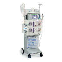
| Type | Hemodialysis machine |
|---|---|
| Manufacturer | Fresenius Medical Care |
| Model | 4008 E |
| Control System | Microprocessor-controlled |
| Heparin pump flow | 0.1 - 10 ml/h |
| Temperature range | 35 - 39 °C |
| Treatment Modes | Hemodialysis, Hemodiafiltration |
| Power Supply | 100-240 V AC |
| Blood Flow Rate | up to 500 ml/min |
| Dialysate Flow Rate | up to 800 ml/min |
| Display | LCD |
| Venous pressure range | +500 mmHg |
| Weight | Approx. 85 kg (187 lbs) without options |
| Ultrafiltration Rate | 0.0 - 4.0 l/h |