Do you have a question about the Fresenius Medical Care 4008 B and is the answer not in the manual?
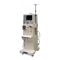
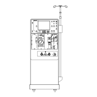
| Type | Hemodialysis Machine |
|---|---|
| Manufacturer | Fresenius Medical Care |
| Model | 4008 B |
| Dialysate Flow Rate | 300 - 800 ml/min |
| Treatment Modalities | Hemodialysis, Hemodiafiltration |
| Blood Flow Rate | 50-500 mL/min |
| UF Rate | 0.0 - 4.0 l/h |
| Power Supply | 50/60 Hz |
Details the T1 test procedure, flow diagrams, and error messages.
Covers essential safety checks and maintenance procedures performed annually.
Details measurement checks and maintenance for optional system features performed every 24 months.
Provides a checklist for Technical Safety Checks to be performed annually.
Explains the process and basic conditions for machine calibration.
Step-by-step guide for calibrating arterial pressure.
Covers calibration of arterial, SN, and HDF blood pump rates.
Procedure for calibrating dialysate temperature.
Procedure for calibrating dialysate pressure.
Explains how to read and interpret analog inputs from CPU I.
Explains how to read and interpret analog inputs from CPU II.
Explains how to read and interpret digital inputs from CPU I.
Explains how to read and interpret digital inputs from CPU II.
Details the process of writing to analog outputs for CPU I.
Presents the AC electrical schematic for 4008 E/H models.
Presents the AC electrical schematic for 4008 B/S models.
Describes the LP 450-2 PCB for level detection, including its operation and circuit.
Describes the LP 493 PCB for blood leak detection, including its principle and circuit.
Describes the LP 624 Control board (BP), its functions, and voltage supply.
Describes the LP 630 Motherboard PCB, its connections, and components.
Describes the LP 631 CPU 1 PCB, its components, and system operation.
