610.020-IOM (NOV 19)
Page 8
EVAPORATOR AND AIR COOLER
INSTALLATION - OPERATION - MAINTENANCE
Defrost
All air coolers operating with coil surface temperatures
beneath freezing (32°F [0°C]) experience some form of
frost accumulation. In order to maintain the performance
of the coil, it is imperative that some form of defrosting
is incorporated into the system. The defrosting of the coil
is accomplished by air, for rooms above 36°F (2.2°C), hot
gas, electric, or water. See Table 3.
AIR DEFROST
For applications where the room temperature is above
freezing, defrosting of the nned surface area is possible
by closing the liquid feed to the coil and allowing the fans
to continue running. The warmer air passing over the coil
melts the frost accumulation but the rate of frost melt is
dependent on the frost formation and room temperature.
Only use air defrost when the room temperature is above
36°F (2.2°C).
HOT GAS DEFROST
Most refrigeration systems incorporate a central compres-
sor room. This is an ideal source for hot gas and only re-
quires the piping to make it available for the evaporators.
The latent heat content of the vapor makes this method of
defrosting very effective and is essentially a by-product of
the refrigeration system. It is essential that not more than
1/3 of the evaporators in the system are defrosted
simultaneously.
Reverse cycle defrost is not recommended for non–
commercial applications. Always use forward cycle, which
requires a three-pipe arrangement at the evaporator, the
third pipe being the hot gas supply line. The hot gas ow
through the unit must always be a series arrangement,
rst through the pan section and then into the coil from
top to bottom. For DX applications using a distributor,
the hot gas feed into the coil must always be through the
distributor, not reverse cycle.
Incorporate a soft start hot gas solenoid valve in the valve
station into evaporators with capacities greater than 15
tons (52 kW). This valve allows the coil to ease up to the
hot gas pressure and prevents problems such as check
valve chatter, liquid hammer, and piping vibrations.
The pump out phase is critical to optimum defrost per-
formance. Additionally, if liquid is still present in the tubes
when the hot gas enters the coil, condensate induced
hydraulic shock is possible, which can have severe conse-
quences including ruptured pipes.
Hot gas piping located within the refrigerated spaces or
outdoors in cold climates must be insulated. It is also
recommended to have liquid drainers installed in these
lines to prevent liquid condensate entering the evaporator
during the defrost phase.
The hot gas mass ow supplied to the evaporator is de-
pendent on the capacity of the unit and the hot gas pres-
sure entering the evaporator. It is insufcient hot gas ow
to the evaporator that results in poor defrost performance,
rather than insufcient hot gas pressure and temperature.
See Table 4 for recommended hot gas pressures at the
evaporator.
The sequence of hot gas defrost operation and recom-
mended stage duration is indicated in Table 5.
ELECTRIC DEFROST
For DX halocarbon applications the most common method
of defrost is with electric heater rods. The heaters are
placed in both the coil and the pan section. The heater
rods are installed within support tubes in the coil bundle
and held in place with C clips, which are positioned so that
there is sufcient space for the rods to expand and con-
tract due to the thermal changes. All heater rods require a
pull space for removal or replacement that is equal to 0.8
x the coil length.
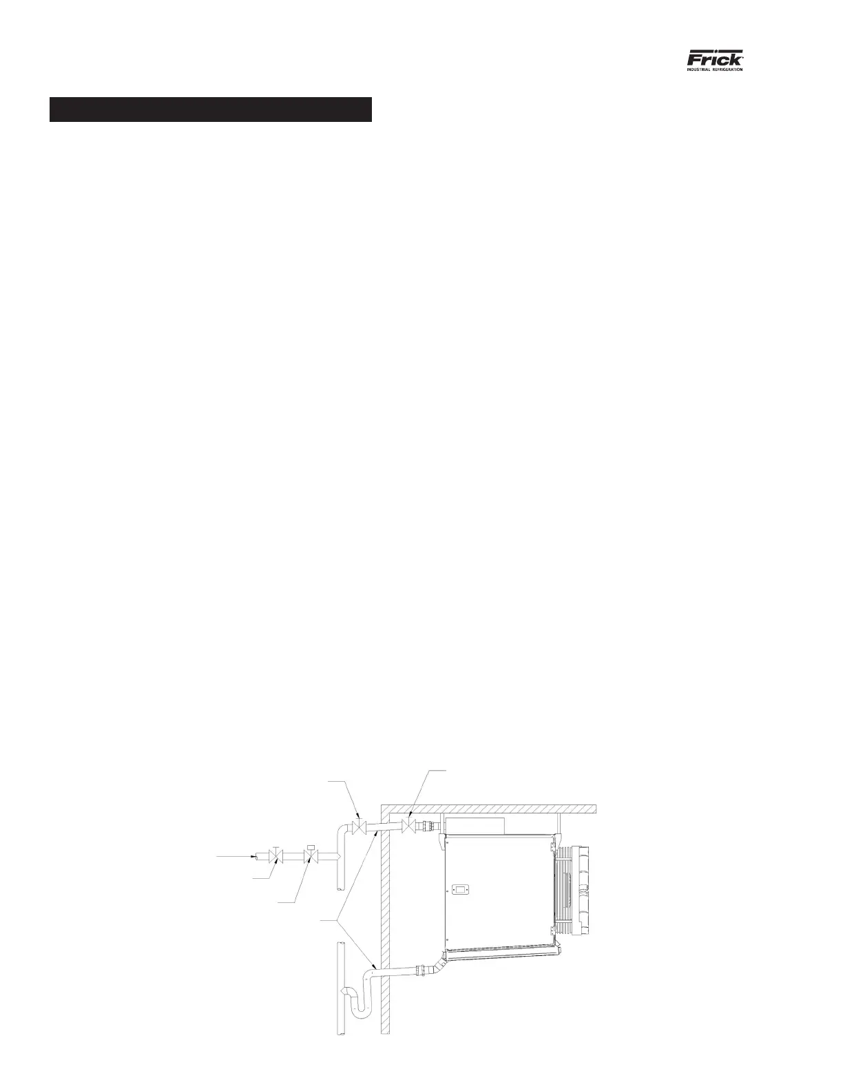
Figure 1: Drain line and water defrost piping
Regulating valve
Main water supply
Shut-off valve
Soleniod valve
Water defrost supply lines and
drain lines pitched 3/8 in. per ft
Regulating valve at each defrost/
unit connection