070.610-IOM (JUL 21)
Page 10
RWF II Rotary Screw Compressor Units
Installation
NOTICE
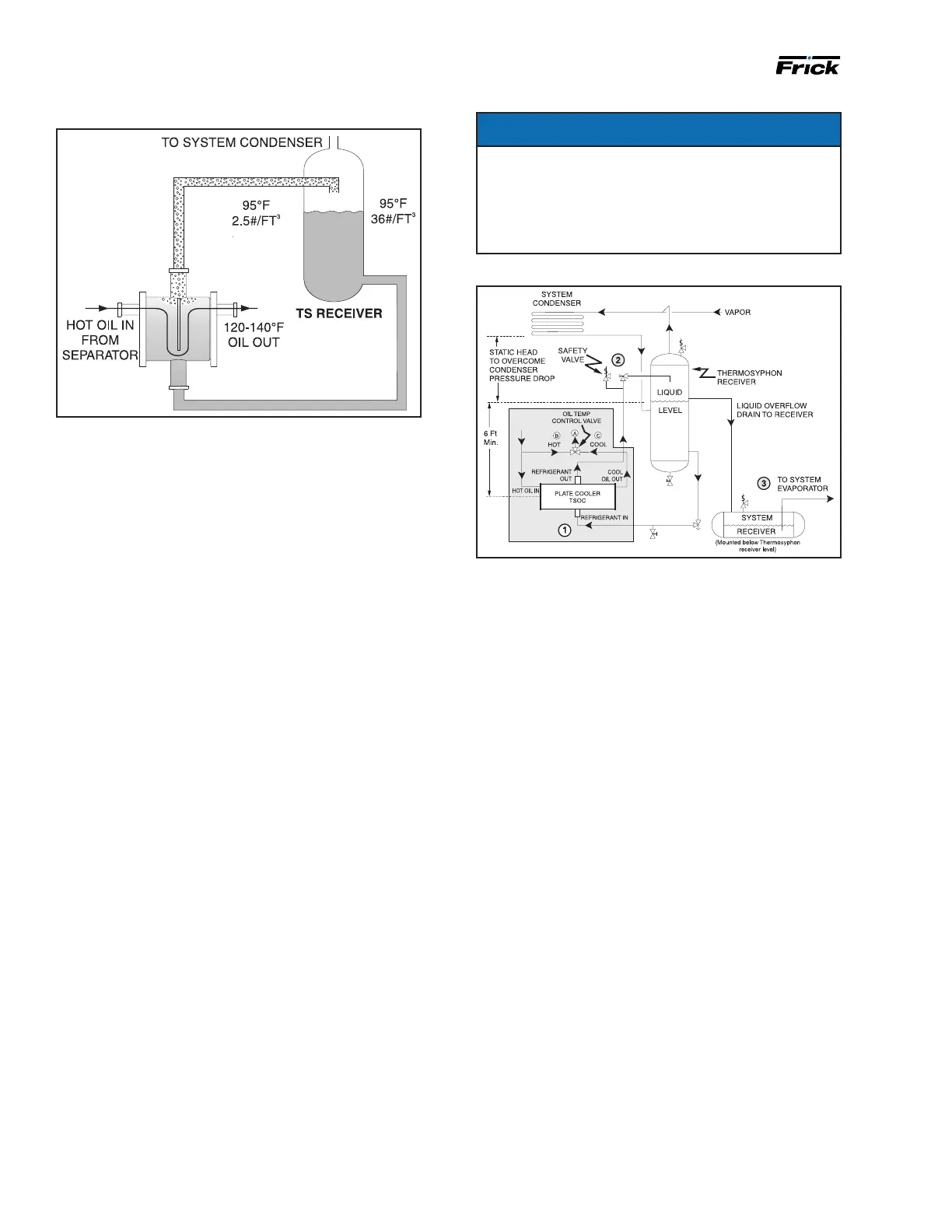
The component and piping arrangement shown in Fig-
ure 10 is intended only to illustrate the operating prin-
ciples of thermosyphon oil cooling. Other component
layouts may be better suited to a specic installation.
Refer to publication 070.900-E for additional informa-
tion on Thermosyphon Oil Cooling.
Figure 10: TSOC Piping Arrangement
1. The thermosyphon oil cooler is supplied with oil side
piped to the compressor unit and stub ends supplied on
the refrigerant side.
2. A refrigerant-side safety valve is required in this loca-
tion only when refrigerant isolation valves are installed be-
tween the cooler and thermosyphon receiver. If no valves
are used between the cooler and TSOC receiver, the
safety valve on the TSOC receiver must be sized to handle
the volume of both vessels. Then, the safety valve on the
cooler vent (liquid refrigerant side) can be eliminated.
3. The system receiver must be below the thermosyphon
receiver in this arrangement.
Liquid injection oil cooling -
optional
The liquid injection system provided on the unit is self-
contained but requires the connection of the liquid line,
sized as shown in Table 6.
It is imperative that an uninterrupted supply of high pres-
sure liquid refrigerant be provided to the injection system
at all times. Two items of extreme impor tance are the
design of the receiver/liquid injection supply and the size
of the liquid line.
It is recommended that the receiver be oversized
sufcient ly to retain a 5-min supply of refrig erant for oil
cooling. The evaporator supply must be secondary to
this consideration. Two methods of accomplishing this are
shown.
The dual dip tube method (see Figure 11) uses two dip
tubes in the receiver. The liquid injection tube is below the
evapor ator tube to ensure continued oil cooling when the
receiver level is low.
Figure 9: Thermosyphon receiver system
System operation - Liquid refrigerant lls the cooler shell
side up to the Thermosyphon receiver liquid level.
Hot oil (above the liquid temperature) owing through
the cooler will cause some of the refrigerant to boil and
vaporize. The vapor rises in the return line. The density
of the refrigerant liquid/vapor mixture in the return line
is considerably less than the density of the liquid in the
supply line. This imbalance provides a differential pres-
sure that sustains a ow condi tion to the oil cooler. This
relationship involves:
1. Liquid height above the cooler.
2. Oil heat of rejection.
3. Cooler size and piping pressure drops.
Current thermosyphon systems are using two-pass oil
coolers and ow rates based on 3:1 overfeed.
The liquid/vapor returned from the cooler is separated in the
receiver. The vapor is vented to the condenser inlet and need
only be reliquied because it is still at condenser pressure.
See Figure 9.
Oil temperature control - Oil temperature will generally
run about 15 - 35°F above condensing tempera ture. In
many cases, an oil temperature control is not required if
condensing temperature is above 65°F as oil tempera ture
can be allowed to oat with condenser temperature.
Condensing Temperature: 65°F to 105°F
Oil Temperature: 80°F to 140°F
Installation - The plate-and-shell type thermosyphon oil
cooler with oil-side piping and a thermostatically con-
trolled mixing valve are factory mount ed and piped. The
customer must supply and install all piping and equip ment
located outside of the shaded area on the piping diagram
with consideration given to the following:
1. The refrigerant source, thermosyphon or system
receiv er, should be in close proximity to the unit to mini-
mize piping pressure drop.
2. The liquid level in the refrigerant source must be 6 ft to
8 ft minimum above the center of the oil cooler.
3. A safety valve should be installed if refrigerant isolation
valves are used for the oil cooler.
 Loading...