070.610-IOM (JUL 21)
Page 11
RWF II Rotary Screw Compressor Units
Installation
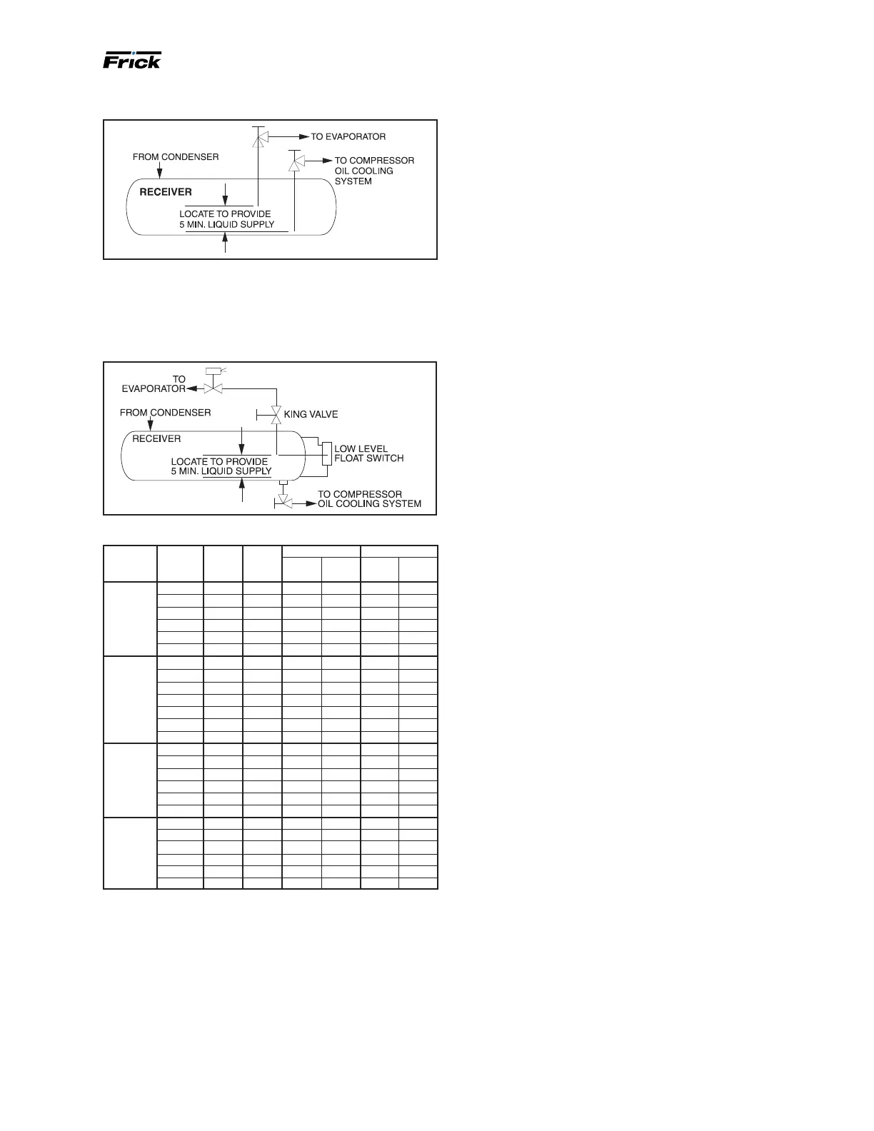
Figure 11: Dual dip tube
The level-control method (see Figure 12) uses a oat level
control on the receiver to close a solenoid valve feeding
the evaporator when the liquid falls below that amount
necessary for 5 min of liquid injection oil cooling.
Figure 12: Level control
Table 6: Liquid line size and receiver volume
Refrigerant RWF II
model
Min.
line
size*
Max.
Lbm/
min
5 min supply
Heat load
lb ft
3
kBtu/hr TR
R-717
high
stage
100-134 0.75 16.0 80 2.2 506 42
177-270 1 32.0 160 4.4 1016 85
316-399 1.25 46.6 233 6.3 1478 123
480-546 1.25 63.8 319 8.7 2022 169
676 1.25 82.4 412 11.2 2613 218
856 1.5 105.2 526 14.3 3335 278
R-717
Booster
100-134 0.5 2.6 13 0.4 85 7
177-270 0.5 4.9 25 0.7 162 14
316-399 0.5 7.2 36 1.0 237 20
480-546 0.75 9.9 50 1.3 326 27
676 0.75 12.6 63 1.7 414 35
856 0.75 16.2 81 2.2 531 44
1080 1 21.0 105 2.9 688 57
R-507
†
high
stage
100-134 1.25 51.3 257 4.1 221 18
177-270 1.5 102.6 513 8.3 441 37
316-399 1.5 149.0 745 12.0 641 53
480-546 2 203.8 1019 16.4 877 73
676 2 266.9 1335 21.5 1149 96
856 2 269.4 1347 21.7 1159 97
R-507
†
Booster
100-134 0.5 8.7 44 0.7 41 3
177-270 0.75 14.7 74 1.2 68 6
316-399 0.75 21.4 107 1.7 99 8
480-546 1 29.3 147 2.4 136 11
676 1 42.1 211 3.4 196 16
856 0.75 9.6 48 0.8 45 4
Conditions: HI Stage: 0°F Evap, and 95°F Cond, 10°F suc-
tion (line) superheat; Booster: -40°F Evap, 95°F Cond and
20°F Intermediate, 10°F suction (line) superheat
* Based on 100 foot liquid line. For longer runs, increase line
size accordingly.
†
Unloaded slide valve.
Water or glycol oil cooling -
optional
The plate-and-shell type water or glycol oil cooler is
mounted on the unit complete with all oil piping. The
customer must supply adequate water connections. De-
termine the size of the oil cooler supplied with the unit,
as outlined on the Frick P&I diagram and general arrange-
ment drawings. The water or glycol supply must be
sufcient to meet the required ow.
The glycol or water entering temperature should be no
lower than 60°F.
A closed-loop system is recommended for the water or
glycol side of the oil cooler. Careful attention to water
treatment is essential to ensure adequate life of the cooler
if cooling tower water is used. It is imperative that the
condition of cooling water or glycol closed-loop uids be
analyzed regularly and as necessary and maintained at a
pH of 7.4, but not less than 6.0 for proper heat exchanger
life. After initial start-up of the compressor package, the
strainer at the inlet of the oil cooler should be cleaned sev-
eral times in the rst 24 hours of operation.
In some applications, the plate and shell oil cooler may
be subjected to severe water conditions, including high
temperature and/or hard water conditions. This causes
accelerated scaling rates which will penalize the perfor-
mance of the heat exchanger. A chemical cleaning process
will extend the life of the plate-and-shell heat exchanger.
It is important to establish regular cleaning schedules.
Cleaning: A 3% solution of phosphoric or oxalic acid is
suggested. You can obtain other cleaning solutions from
your local distributor, but they must be suitable for stain-
less steel. It is possible to clean the oil cooler in place by
back ushing with suggested solution for approximately
30 min. After back ushing, rinse the heat exchanger with
fresh water to remove any remaining cleaning solution.
High-stage economizer - optional
The economizer option provides an increase in system
capacity and efciency by subcooling liquid from the
condenser through a heat exchanger or ash tank before
it goes to the evapora tor. The subcooling is provided by
ashing liquid in the economizer cooler to an intermediate
pressure level. The intermediate pressure is provided by a
port located part way down the compres sion process on
the screw compressor.
As the screw compressor unloads, the economizer port
will drop in pressure level, eventually being fully open to
suction. Because of this, an output from the microproces-
sor is generally used to turn off the supply of ashing
liquid on a shell and coil or DX economizer when the
capacity falls below approximately 60% to 70% capacity
(85% to 90% slide valve position). This is done because
the compressor will be more efcient operating at a higher
slide valve position with the economizer turned off, than
it will at a low slide valve position with the economizer
turned on. Please note however that shell and coil and DX
economizers can be used at low compressor capaciti es in
cases where efcien cy is not as important as assuring that
the liquid supply is subcooled. In such cases, the economi-
zer liquid solenoid can be left open whenever the com-
pressor is running.
 Loading...