070.610-IOM (JUL 21)
Page 7
RWF II Rotary Screw Compressor Units
Installation
Install the locknut until it is snug. Make sure that all bolt
threads are clean and lightly oiled. Do not torque any lock-
nuts at this time. Now pivot the unitized ex disc until the
other bushing holes in the ex disc are in line with the bolt
holes in the spacer. Install the rest of the spacer bolts at
this time. The remaining bolts for this end of the coupling
can be installed through the hub bolt holes and ex disc
bushing holes.
Install the unitized ex disc in the other end of the cou-
pling. The unitized ex disc, as installed, should look at
and parallel with the mating hub and spacer anges.
Torque the disc pack locknuts as suggested in Table 3.
The bolts should be held in place while the locknuts are
torqued.
3. Center the coupling between the shafts. Ensure that
the keys are fully engaged in their keyways.
4. Tighten the motor and compressor shaft clamping bolts
evenly. Torque to the recommended specication in
Table 3.
5. Torque the keyway setscrews as recommended in
Table 3.
NOTICE
Only after the shaft clamping bolts are tightened to
their nal torque can the keyway set screws be tight-
ened. If the keyway set screws are tightened before
the shaft clamping bolts are tightened, then the hubs
can be cocked on the shaft.
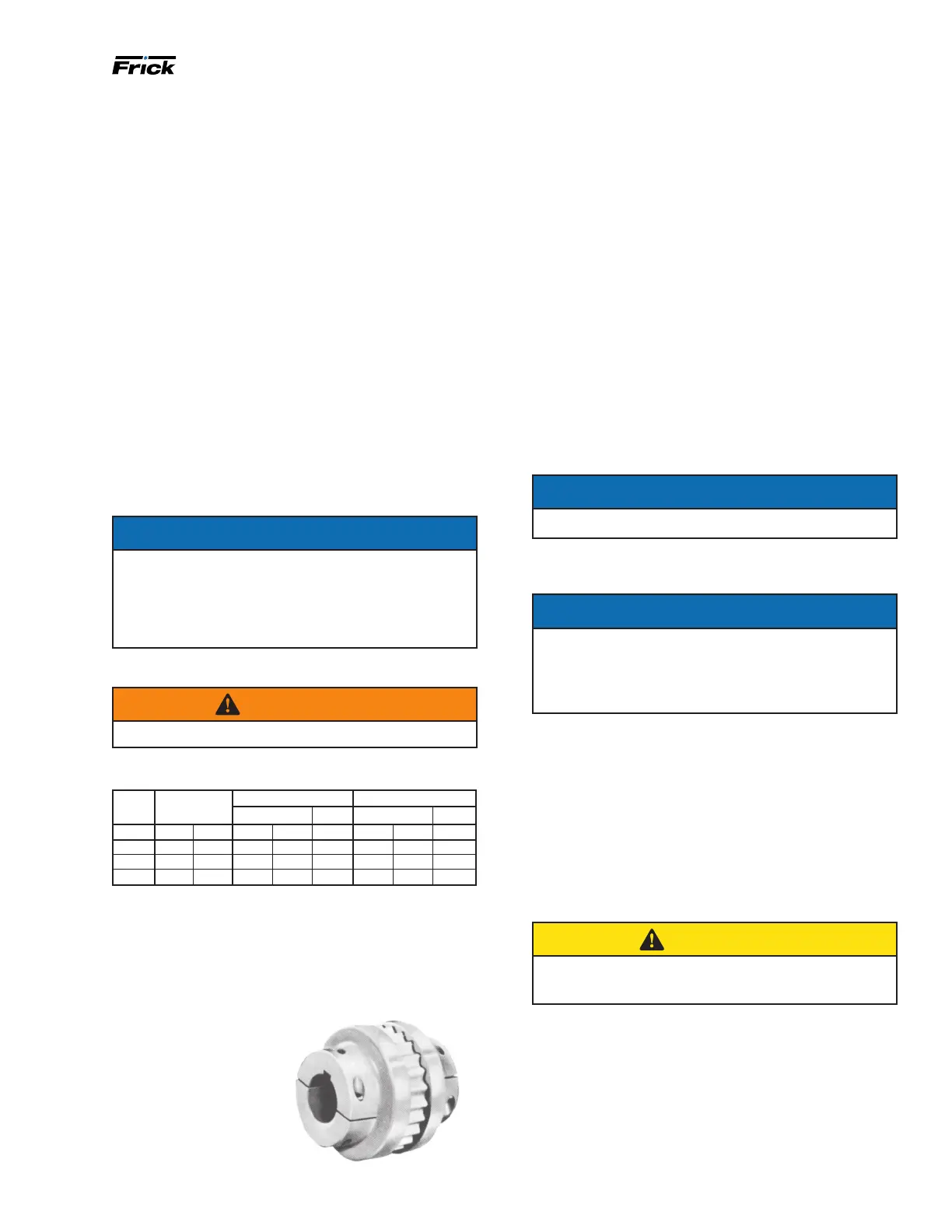
CH Series coupling
WARNING
CH couplings are not to be used over 3600 rpm.
Table 4: CH Series coupling data
CH
series
Face
spacing
Clamp bolt
Keyway setscrew
Torque (dry) Size Torque Size
Size in. mm ft-lb N.m
UNF
ft-lb N.m
UNC
9 1
7
⁄16 36.5 55 74.6
3
⁄8-24 13 17.6
5
⁄16 -18
10 1
11
⁄16 42.9 130 176.3 ½ -20 13 17.6
5
⁄16 -18
11 1
7
⁄8 47.6 130 176.3 ½ -20 13 17.6
5
⁄16 -18
CH coupling installation procedure
The CH Coupling is used in most applications. This cou-
pling consists of two drive hubs and a gear-type Hytrel or
EDPM and neoprene drive spacer. The split hub is clamped
to the shaft by tightening
the clamp screws. Torque
is transmitted from the motor
through the elastomeric gear
which oats freely between
the hubs. Because of the
use of the motor/compres-
sor adapter housing on the
RWF II, no eld alignment is
necessary.
1. Inspect the shaft of the motor and compressor to en-
sure that no nicks, grease, or foreign matter is present.
2. Inspect the bores in the coupling hubs to make sure
that they are free of burrs, dirt, and grit.
3. Check that the keys t the hubs and shafts properly.
4. Slide one hub onto each shaft as far as possible. It may
be necessary to use a screwdriver as a wedge in the slot
to open the bore before the hubs will slide on the shafts.
5. Rotate both hubs so that the keys are 180° opposed.
6. Hold the elastomeric gear between the hubs and slide
both hubs onto the gear to fully engage the mating teeth.
Center the gear and hub assembly so there is equal en-
gagement on both shafts. Note that the hubs may over-
hang the ends of shafts. Adjust the face spacing between
hubs as specied in the Table 4. Ensure that the keys are
fully engaged in their keyways.
7. Torque the clamping bolts in both hubs to the torque
value given in the Table 4.
NOTICE
DO NOT USE ANY LUBRICANT ON THESE BOLTS.
8. Torque the keyway setscrew in both hubs to the torque
value given in the Table 4.
NOTICE
Only after the shaft clamping bolts are tightened to
their nal torque can the keyway set screws be tight-
ened. If the keyway set screws are tightened before
the shaft clamping bolts are tightened, then the hubs
can be cocked on the shaft.
Oil pump coupling
Compressor units with direct motor/pump coupled pumps
need no pump/motor coupling alignment since this is
maintained by the close-coupled arrangement.
Holding charge and storage
Each RWF II compressor unit is pressure and leak tested
at the factory and then thoroughly evacuated and charged
with dry nitrogen to ensure the integrity of the unit during
shipping and short-term storage before installation.
CAUTION
Care must be taken when entering the unit to ensure
that the nitrogen charge is safely released.
Figure 6: CH coupling
 Loading...