070.610-IOM (JUL 21)
Page 6
RWF II Rotary Screw Compressor Units
Installation
The unit can be moved with rigging, using a crane and
spreader bar, by hooking into the four lifting eyes on the
oil separator. If a motor is mounted, ap propriate adjust-
ment in the lifting point should be made to compensate
for motor weight. Adjustment of the lifting point must also
be made for any additions to the standard package such as
an external oil cooler, etc., because the center of balance
will be affected. Refer to supplied engineering drawings to
determine the package center of gravity.
The unit can be moved with a forklift by forking under the
skid, or it can be skidded into place with pinch bars by
pushing against the skid. Never move the unit by pushing
or forking against the separat or shell or its mounting
supports.
Skid removal
If the unit is rigged into place, the skid can be removed
by taking off the nuts and bolts that are fastening the unit
mounting supports to the skid before lowering the unit
onto the mounting surface.
If the unit is skidded into place, remove the cross mem bers
from the skid and remove the nuts anchoring the unit to
the skid. Using a 10-ton jack under the separator raise the
unit at the compressor end until it clears the two mounting
bolts. Spread the skid to clear the unit mounting support,
then lower the unit to the surface. Repeat proced ure on
opposite end.
Check the motor/compressor rotation.
WARNING
Make sure coupling hubs are tightened to the shaft
before rotating the motor to prevent them from ying
off and possibly causing serious injury or death.
WARNING
Injury may occur if loose clothing, etc, becomes en-
tangled on the spinning motor shaft.
Compressor rotation is
clockwise when facing
the end of the compressor
shaft. Under no conditions
should the motor rota-
tion be check ed with the
coupling center installed as
damage to the com pressor
may result. Bump the motor
to check for correct compressor rotation. After verica-
tion, install disc drive spacer (metal center section or
elastomeric gear) as applicable.
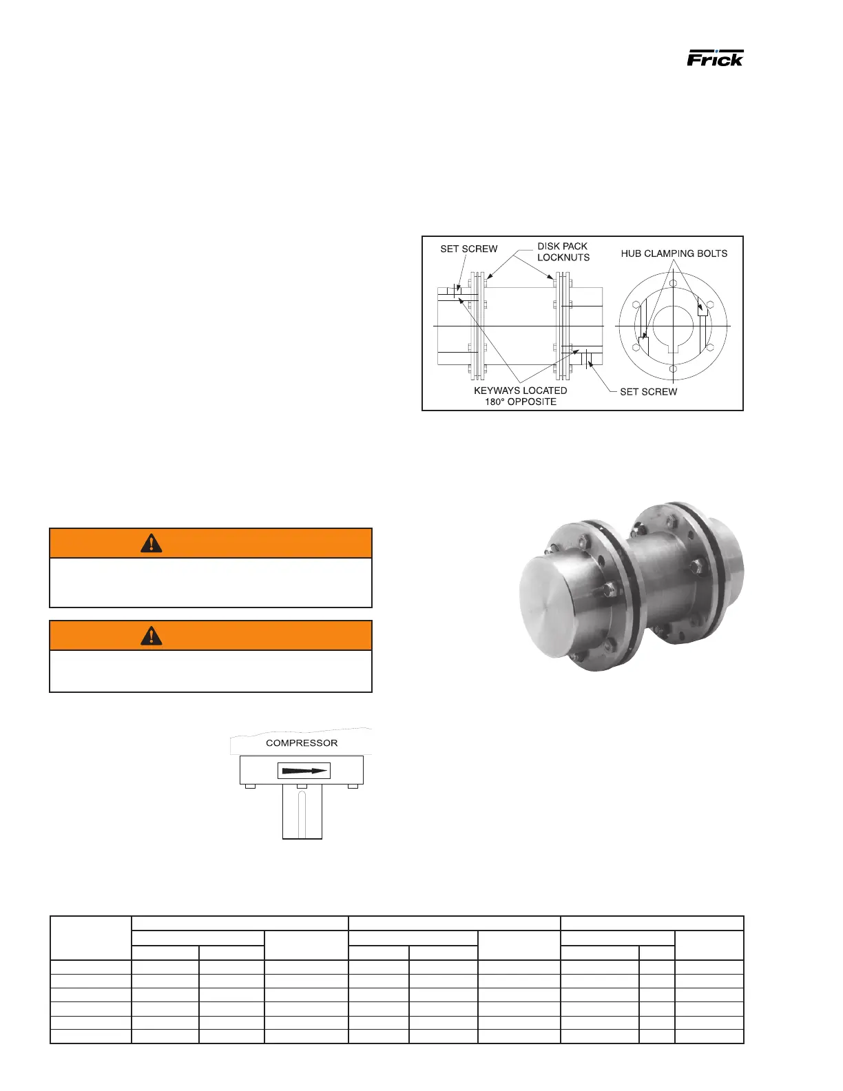
Compressor/motor coupling
installation
The RWF II unit has compressor to motor alignment
through the use of a machined cast iron tunnel. This tun-
nel is factory set through machining tolerances ensuring
motor compressor alignment. No alignment is required in
the eld. See Figure 4.
Figure 4: BP coupling diagram
BP coupling installation procedure
1. Install the motor and compressor coupling hubs and
keys on their respective shafts. Ensure that they can slide
horizontally so
that once the
disc packs are
installed, no axial
stress is trans-
ferred to the disc
packs by a stuck
coupling hub.
Use no lubri-
cants.
2. Rotate both
hubs so that the
keys are 180° op-
posed. With the hubs mounted and the axial spacing set,
proceed to place the spacer between the two hub anges.
Care should be taken when handling the spacer. Be sure
the spacer is fully supported at this time. Damage to the
unitized ex discs may result after they have been installed
if the spacer is not fully supported.
Install the unitized ex disc. Start a bolt through a bolt
hole in the spacer. Put the unitized ex disc between
the hub and spacer until a bushing hole in the unitized
ex disc lines up with the bolt. Slide the bolt through the
bushing hole in the unitized ex disc. To avoid thread
damage, ensure that every other bolt is installed in the
opposite direction as shown in the photo.
Table 3: BP series coupling data table
BP
series
size
Disc pack locknut Hub clamping bolts Keyway setscrew
Torque (lube*) Size UNF Torque Size UNF Torque Size NC
ft-lb N
.
m ft-lb N
.
m ft-lb N
.
m
BP 38 17 23.1 5/16-24 41 55.6 3/8-24 22 29.8 3/8-16
BP 43 40 54.2 7/16-20 41 55.6 3/8-24 22 29.8 3/8-16
BP 48 40 54.2 7/16-20 41 55.6 3/8-24 53 71.9 1/2-13
BP 53 60 81.4 1/2-20 66 89.5 7/16-20 53 71.9 1/2-13
BP 58 120 162.7 5/8-18 101 137.0 1/2-20 53 71.9 1/2-13
BP 63 120 162.7 5/8-18 101 137.0 1/2-20 186 252.2 3/4-10
Figure 5: BP coupling
Figure 3: Direction of rotation
 Loading...