070.650-IOM (JUL 19)
Page 32
SGC/SGX ROTARY SCREW COMPRESSOR
INSTALLATION
A
P
DIRECTION
CONTROL VALVE
SV-2
Valve 1
Valve 1
Valve 2
Valve 2
P
T
SC2
1
P
T
A
B
2
SC1
SC1
1
1
BP
1
2
SC2
2
2
SC3
SC3
SCREW IN FLOW
REGULATING
NEEDLE VALV E
SV-3
1
T
B
SC4
2
SC4
DIRECTION
CONTROL
VALV E
HYDRAULIC SCHEMATIC
SGC 1913 – 2824
P
T
YY4 (DECREASE VI)
YY2 (LOAD)
(INCREASE VI) YY3
(UNLOAD) YY1
SC4
BP
SC2
SC3
SC1
YY1
YY2
YY3
YY4
SC3
2
SC4
SC3
1
2
SC2
SC1
2
SC2
1
1
2
A
B
1
P
T
BP
B
A
T
P
SC1
SV-3
T
HYDRAULIC SCHEMATIC
SGC 3511 – 3524
P
SV-2
SCREW IN FLOW
REGULATING
NEEDLE VALV E
SC 4 NOT USED
DIRECTION
CONTROL VALVE
SC-5
SP-1
YY2 (LOAD)
YY4 (DECREASE VI)
COMPRESSOR TOP VIEW
COMPRESSOR TOP VIEW
YY1
YY2
YY3
YY4
(UNLOAD) YY1
(INCREASE VI) YY3
ENDVIEW
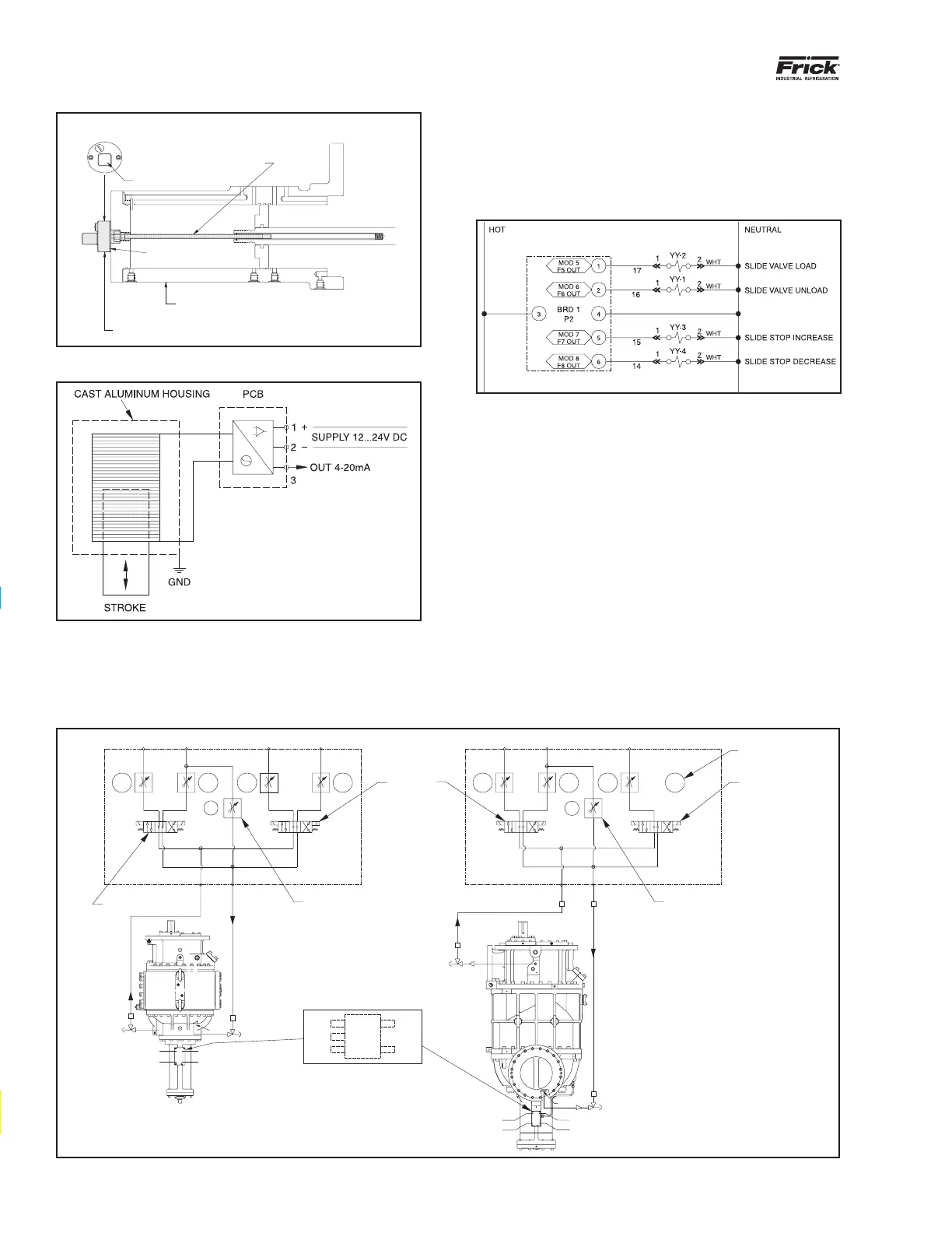
DIN CONNECTOR
STAINLESS STEEL WELL
HEAT ISOLAT OR
CAST ALUMINUM HOUSING
COMPRESSOR UNLOAD CYLINDER
SHADED AREA SHOWS
CAPACITY LINEAR TRANSMITTER
Figure 23: Capacity slide valve transmitter
Figure 24: Wiring diagram for slide valve transmitter
DIRECTIONAL CONTROL VALVES
Solenoids YY1, YY2, YY3 and YY4 must be wired to give
the correct function. A description of their function is given
in the OPERATION chapter. For control system information
refer to 090.040-O - FRICK Compressor Control Panel. See
wiring diagram in Figure 25.
Figure 25: Directional control valve wiring diagram
COMPRESSOR HYDRAULIC SYSTEM
(The solenoid valves and manifold block are available as
a sales order option - See Figures 20 and 21)
The compressor hydraulic system actuates the movable slide
valve (SV) to load and unload the compressor. It also actu-
ates the movable slide stop (SS) to increase or decrease the
compressor’s volume ratio (Vi). The hydraulic cylinder located
at the inlet end of the SGC compressor serves a dual purpose.
It is separated by a xedbulkhead into two sections. The
SV section is to the left of the bulkhead and the SS is to the
right if you are facing the right side of the compressor. Both
operations are controlled by double-acting, four-way solenoid
valves, which are actuated when a signal from the appropriate
microprocessor output energizes the solenoid valve.
Figure 26: Hydraulic Schematic, SGC 1913 - 2824, SGC 3511 - 3524
need info for 408?
updated text