65 PB
COMPONENT TESTING
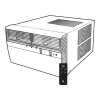
Replace the Electronic Control Board
Replace the User Interface
1.Unplug the Unit
Remove the Front Cover. Refer to Routine Maintenance, Figure 401.
2. Remove 2 –mounting screws securing UI and disconnect ribbon
cable.
2. Inspect ribbon cable for obvious signs of damage.
2. If ribbon cable is damaged, or damage is suspected, disconnect
cable from User Interface and Control Board.
3. Paying careful attention to the ribbon cable routing, remove the old
cable and replace with a new ribbon cable.
4. Connect ribbon cable to the power board and user interface as
required.
Step 4. Install new UI using the 2-screws.
Step 5. Plug in the unit and verify control operation. Refer to Operation
Section.
WARNING
ELECTRIC SHOCK HAZARD
Turn off electric power before service or
installation. Extreme care must be used, if it
becomes necessary to work on equipment with
power applied.
Failure to do so could result in serious injury or
death.
WARNING
ELECTRIC SHOCK HAZARD
Turn off electric power before service or
installation. Extreme care must be used, if it
becomes necessary to work on equipment with
power applied.
Failure to do so could result in serious injury or
death.
1. Unplug the unit
2. Remove the Front Cover. Refer to Routine
Maintenance, Figure 401.
3. Remove three (3) screws from Control Box
Panel .
4. If necessary, cut wire ties and remove one(1)
screw from electronic holder to create slack in
wiring.
5. Remove the four(4) circuit Board pins using
needle nose pliers or other suitable tool.
6. If Jumper is installed on High pressure switch
terminals, Swap jumper from old control board
to new control board.
7. Swap wires one for one from old control
board to new control board. If swapping wires
one for one is not possible, identify and tag
wires. Refer to the wiring diagrams as required.
8. Install the control board using four(4) new
circuit board pins.
9. Install sh paper as insulation between
contol board and matal. Secure with the circuit
board pins.
10.Reinstall the control board panel, reinstall
the screw in the electronic holder, and secure
wiring as required.
11. Install the Front Cover (refer to Routine
Maintenance, Figure 401
12. Plug in the unit and test the unit for proper
operation. Refer to operation section.
ID COIL SENSOR (PTU 10)
HARNEES DISPLAY (PTU 50)
TEMP SENSOR DISCH AIR (PTU 50)
TEMP SENSOR AMB TEMP
SCREW X5
RAC MASTER POWER/RELAY MODULE SMPS
SUPPLY CORD
CONTROL BOARD
PANEL
HEATER WIRES
CIRCUIT BOARD PIN X4
Figure 713 (Electronic Control Board Replacement)
 Loading...